605-01-378 5
NOTICE: Medium-strength thread-lock is recommended on all bolts.
1. Please read the installation guidelines on page 4 for instructions on how to properly lift and secure the
vehicle.
2. Record the front vehicle ride height to ensure proper lift is attained after kit is installed. READ
INSTALLATION GUIDELINES ON HOW TO PROPERLY ADJUST PRELOAD.
3. Remove both front wheels from the vehicle.
FRONT SHOCK INSTALLATION
STOCK SHOCK REMOVAL
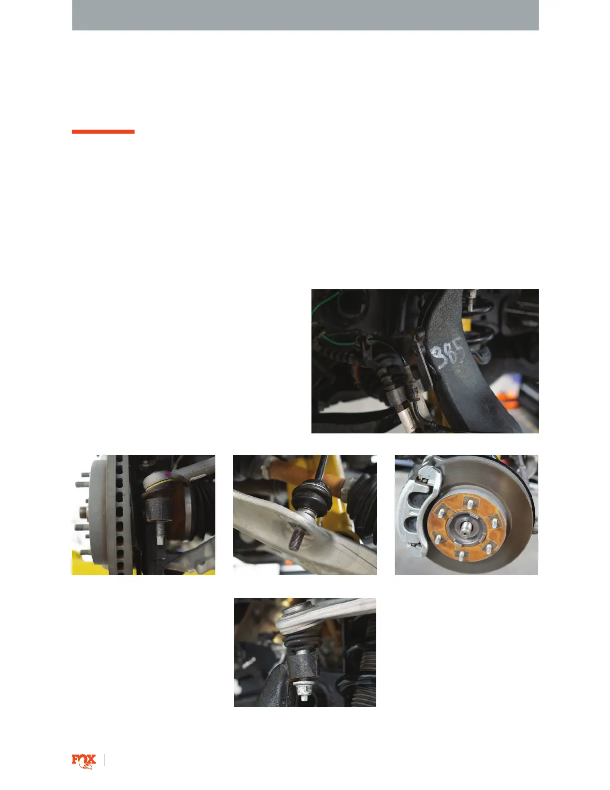
4. Disconnect the brake line bracket from the
upright (Fig. 1).
Fig. 1: Disconnect brake line bracket.
5. Detach the tie rod end link at the spindle steering
arm for removal and installation clearance (Fig. 2).
6. Disconnect the sway bar end link from both lower
control arms (Fig. 3).
7. Remove the axle nut from the upright (Fig. 4).
Push the axle shank flush with the face of the rotor.
Fig. 2: Tie rod end link. Fig. 3: Sway bar end link. Fig. 4: Push the axel shank flush.
8. Remove the nut connecting
the upper control arm (UCA) to
the upright (Fig. 5) Separate the
UCA from the upright.
Fig. 5: Separate the UCA from the upright.