Do you have a question about the Foxconn 915PL7AE series and is the answer not in the manual?
| Form Factor | ATX |
|---|---|
| Socket Type | LGA 775 |
| Chipset | Intel 915PL |
| Front Side Bus | 800/533 MHz |
| Memory Type | DDR |
| Memory Slots | 2 x DIMM |
| Maximum RAM | 2 GB |
| Expansion Slots | 1 x PCIe x16, 3 x PCI |
| Onboard LAN | Realtek RTL8100C 10/100 Mbps |
| PS/2 | 2 |
| USB Ports | 8 x USB 2.0 |
| Supported CPU | Intel Pentium 4, Celeron D |
| IDE | 1 x ATA100 |
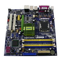
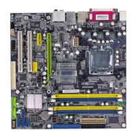
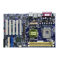
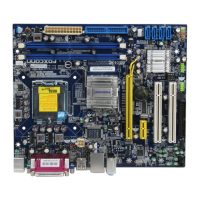
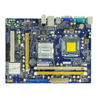
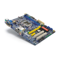
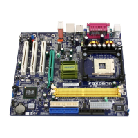
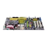
Details key hardware specifications and features of the motherboard.
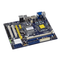
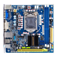
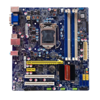
Diagram of motherboard components and connector locations.
Step-by-step guide for CPU installation into the motherboard socket.
Instructions for installing DDR memory modules into DIMM slots.
Guides for connecting ATX power supply connectors to the motherboard.
Description and identification of motherboard rear panel ports.
Details internal connectors: FDD, IDE, front panel, fan headers.
Information on PCI, PCI Express x1, x16, and F.G.E. slots.
Explanation of jumper settings and their configuration.
Procedure to access BIOS Setup utility during system startup.
Explanation of main BIOS menu options and navigation.
Configuration settings for date, time, and IDE devices.
Configuration of system features: SuperBoot, Virus Warning, SuperSpeed.
Detailed settings for CPU features, boot priority, and security.
Configuration for DRAM timings, PCI Express, and memory settings.
Settings for onboard IDE, SATA, and integrated devices.
Configuration of ACPI, suspend types, and power saving options.
Settings for Plug and Play, PCI slot init, and resource control.
Monitoring system temperatures, voltages, and fan speeds.
Options to load Fail-Safe or Optimized BIOS defaults.
Procedure to set Supervisor or User passwords for system access.
Instructions for saving changes and exiting BIOS setup.
Overview of software and drivers on the included motherboard utility CD.
Guide to installing essential drivers and software from the CD.