Chapter 2 Installation Instructions
13
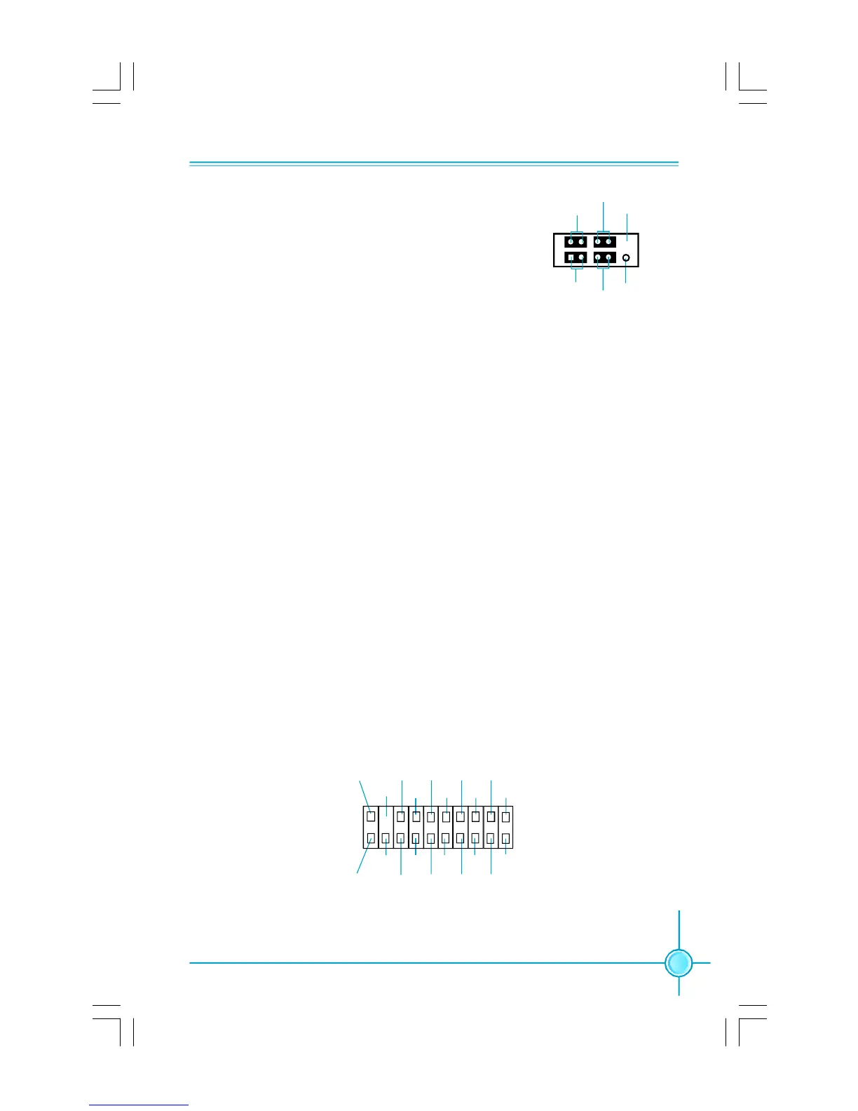
Front Panel Connector: FP1
This motherboard includes one connector for con-
necting the front panel switch and LED indicators.
HDD LED Connector (HD-LED)
The connector connects to the case’s HDD indicator LED indicating the activity
status of hard disks.
Reset Switch (RESET)
Attach the connector to the Reset switch on the front panel of the case; the
system will restart when the switch is pressed.
Power LED Connector (PWRLED)
Attach the connector to the power LED on the front panel of the case. The Power
LED indicates the system’s status. When the system is in S0 status, the LED is
on. When the system is in S1 status, the LED is blink; When the system is in S3,
S4, S5 status, the LED is off.
Power Switch Connector (PWRSW)
Attach the connector to the power button of the case. Pushing this switch allows
the system to be turned on and off rather than using the power supply button.
+ -
+ -
1
FP1
NCHD-LED
RESET
PWRLED
PWRSW
Empty
TPM
CK_33M_TPM
Empty
L_FRAMEJ
2
1
20
19
GND
ICH_P_PCIRSTJ
NC
L_AD3
3D3V_SYS
L_AD0 NC
GND
NC
LPCPDJ
L_AD2
L_AD1
GND
NC
SERIRQ NC
GND
TPM Connector: TPM (optional)
The TPM(Trusted Platform Module) provides the ability to the PC run applications
more secure and to make transactions and communication more trustworthy. To
utilize this function, you should purchase additional devices and install the driver.
PDF 文件使用 "pdfFactory" 试用版本创建 www.fineprint.com.cn
 Loading...