Chapter 2 Installation Instructions
15
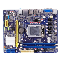
Serial ATA II Connectors: SATA_1, SATA_2,
SATA_3, SATA_4
1
SATA_1/2/3/4
GND
GND GND
RX+
RX-TX-
TX+
The Serial ATA II connector is used to connect
the Serial ATA II device to the motherboard. These
connectors support the thin Serial ATA II cables
for primary storage devices. The current Serial
ATA II interface allows up to 300MB/s data trans-
fer rate.
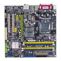
Chassis Intruder Connector: INTR
The connector connects to the chassis secu-
rity switch on the case. The system can detect
the chassis intrusion through the status of this
connector. If the connector has been closed
once, the system will send a message. To uti-
lize this function, set “Case Open Warning” to
“Enabled” in the “PC Health Status” section of
the CMOS Setup. Save and exit, then boot the
operating system once to make sure this func-
tion takes effect.
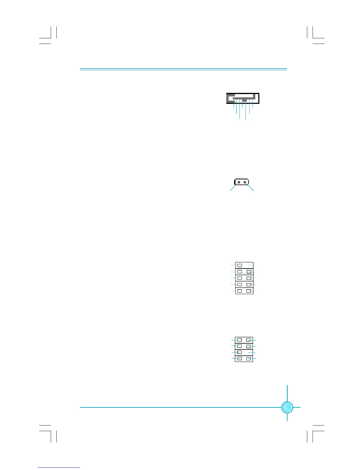
USB Headers: F_USB1, F_USB2
Besides four USB ports on the rear panel, the
series of motherboards also have two headers
on board which may connect to front panel USB
cable (optional) to provide additional four USB
ports.
INTR
1 INTRUDERJ 2 GND
F_USB 1/2
1
5V_DUAL
D-
D+
D-
GND
GND
D+
NC
Empty
5V_DUAL
SPI Connector: SPI (optional)
This motherboard provides a SPI connector,
which is used to flash the SPI BIOS. Connect
one side of a cable to the connector, then attach
the BIOS Flash Card to the other side of the
cable.
7 8
1
2
3D3V_SYS
SPI_HOLDJ
ICH_SPI_CLK
ICH_SPI_MOSI
ICH_SPI_CSJ
ICH_SPI_MISO
Key
GND
SPI
PDF 文件使用 "pdfFactory" 试用版本创建 Æ Æ www.fineprint.com.cn
 Loading...