Chapter 2 Installation Instructions
16
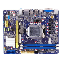
Additional COM Connector: COM2
This motherboard provides an additional serial COM
header for your machine.
Connect one side of a switching cable to the header,
then attach the serial COM device to the other side of
the cable.
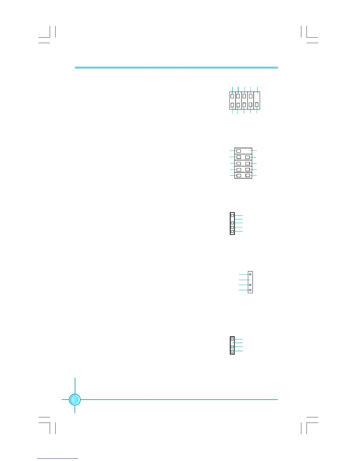
S/PDIF Out Connector: SPDIF_OUT
The SPDIF OUT connector is capable of providing
digital audio to external speaker or compressed AC3
data to an external Dolby digital decoder.
Note:The empty pin of SPDIF cable should be aligned
to empty pin of SPDIF out connector.
SPDIF_OUT
1
SPDIF_OUT
+5V
GND
Empty
IrDA Connector: IR
This header supports wireless transmitting and re-
ceiving device. Before using this function, configure
the settings of IR Mode from the “Integrated Periph-
erals” section of the CMOS Setup.
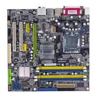
1394 Connector: F_1394 (optional)
The 1394 expansion cable can be connected to ei-
ther the front (provided that the front panel of your
chassis is equipped with the appropriate interface)
or real panel of the chassis.
COM2
SOUT
GND RLSD RI#
DTR#
DSR# SIN
9
10
1
2
CTS#
RTS#
Empty
12
GND
+12V
TPB -
GND
TPA -
+12V
TPB +
GND
TPA +
Empty
F_1394
910
IR
1
+5V
GND
IRRX
IRTX
Empty
Speaker Connector: SPEAKER(optional)
The speaker connector is used to connect speaker
of the chassis.
SPEAKER
1
SPKJ
NC
SPKJ
Empty
PDF 文件使用 "pdfFactory" 试用版本创建 Æ Æ www.fineprint.com.cn
 Loading...