EPS Box -TP Series User Manual www.fox-ess.com P a g e | 6
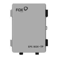
Step 4: Install the expansion screws with screwdriver to fix the EPS Box-TP.
4. Wiring Connection
Step1: Grid String Connection
EPS Box-TP is designed for three-phase grid. Per voltage range is 220/230/240V; frequency is
50/60Hz. Other technical requests should comply with the requirement of the local public grid.
Step 2: Grid Wiring
• Check the grid voltage and compare with the permitted voltage range (refer to technical data).
• Disconnect the circuit-breaker from all the phases and secure against re-connection.
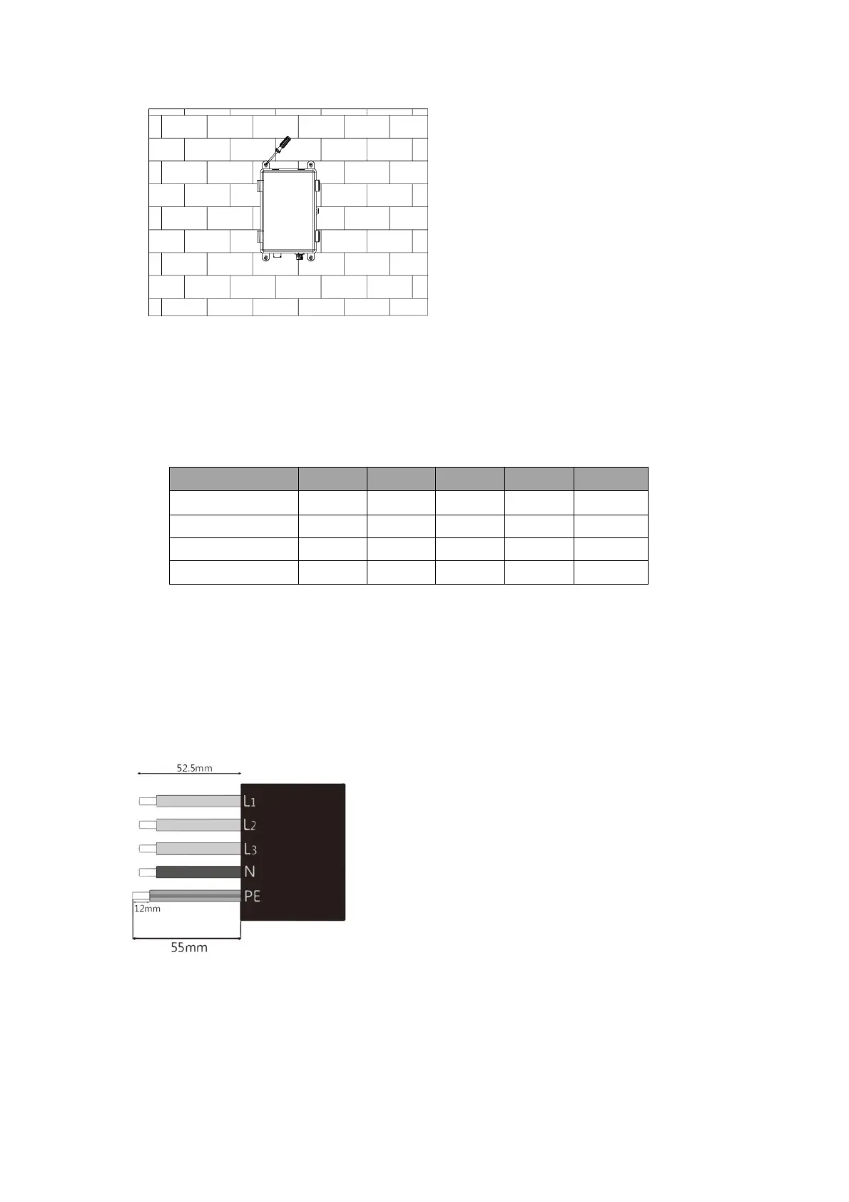
• Trim the wires:
-Trim all the wires to 52.5mm and the PE wire to 55mm.
-Use the crimping pliers to trim 12mm of insulation from all wire ends as below.
L1/L2/L3: Brown/Red/Green or Yellow Wire
N: Blue/Black Wire
PE: Yellow & Green Wire
Note: Please refer to local cable type and color for actual installation