28
Note:
• Isolation Fault
This inverter complies with IEC 62109-2 clause 13.9 for earth fault alarm monitoring. If an Earth Fault
Alarm occurs, the fault code Isolation fault will be displayed on the inverter screen and the RED LED
indicator will light up.
• Reactive Power Regulation for Voltage Variation (Volt-VAr Mode)
Details of how to enable this mode are contained in the “Advanced Configuration Guide”, which can be
accessed at our website at https://www.foxess.com.
• Power Derating for Voltage Variation (Volt-Watt Mode)
Details of how to enable this mode are contained in the “Advanced Configuration Guide”, which can be
accessed at our website at https://www.foxess.com.
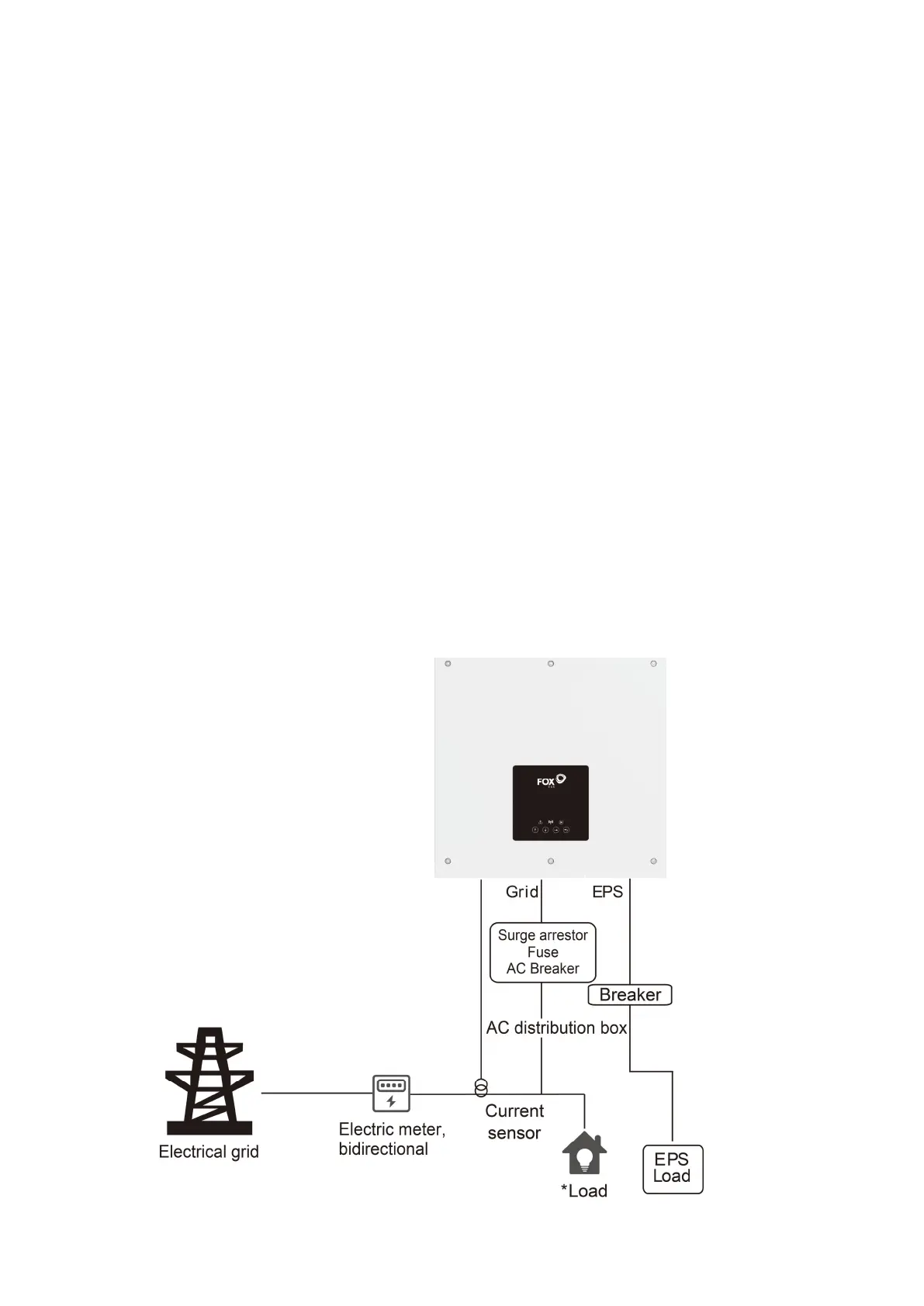
6.6 EPS Connection
A. EPS Wiring
EPS mode can be achieved by two different type of wiring methods. One is using the internal bypass to
wire the house emergency loads on the EPS port from inverter. Another is using external contactor to
wire the EPS loads on the contactor self (External contactor need to be purchased separately).
Note: the inverter default is set as “External” EPS wiring mode, it can be set to “Internal” via
display setting “Menu – Setting – Feature – Bypass Relay”.
• Use Internal EPS Wiring: