26
C. Off-Grid Parallel Connection
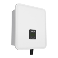
H3/AC3 series Inverters provide the parallel connection function which should make ten inverters
maximumly connected in one system when the grid is off. In this system, one inverter will be set as the
"Master inverter" which will control every other inverter's energy management and dispatch control. Only
one meter needs to be connected in this system and communicate with the "Master inverter", and all
other slaver inverter communicate with "Master inverter" by CAN communication-parallel connection.
Please note the parallel connection function can only be used when the grid is off.
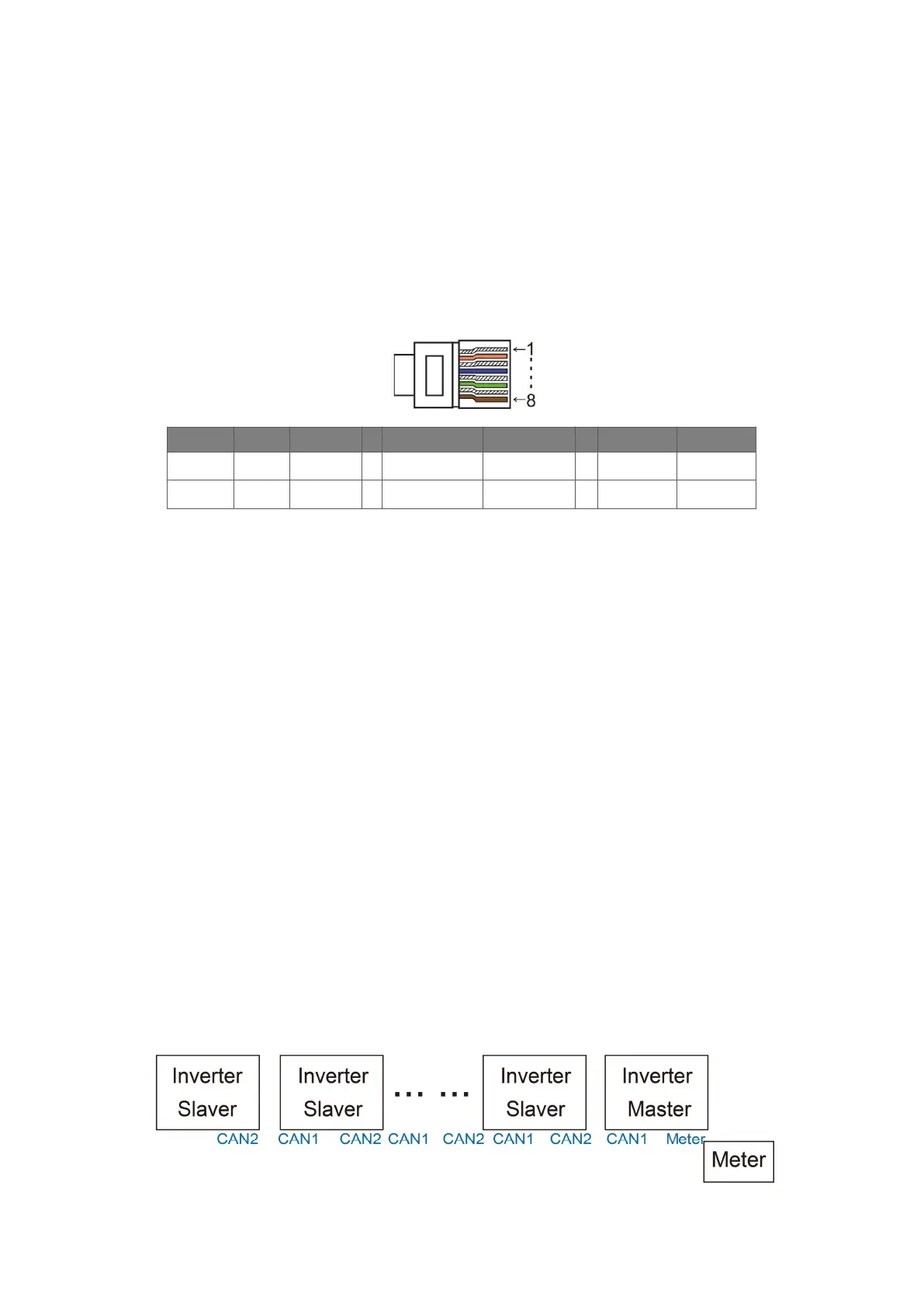
Parallel 1/2 are the ports used in parallel.
Note: The above features are under development.
PIN 1 2 3 4 5 6 7 8
Parallel 1
/ / / Parallel_CANH Parallel_CANL / BMS-CANH BMS-CANL
Parallel 2
E_STOPGND_COM / Parallel_CANH Parallel_CANL / / /
Work Modes in parallel system
There are three work modes in parallel system, and your acknowledge of different inverter’s work modes
will help you understand parallel system better, therefore please read it carefully before operating.
Free mode: Only if no one inverter is set as a “Master”, all inverters are in free mode in the system.
Master mode: When one inverter is set as a “Master”, this inverter enters master mode. Master mode
can be changed to free mode or slaver mode by LCD setting.
Slaver mode: Once one inverter is set as a “Master”, all other inverters will enter slaver mode
automatically. Slaver mode cannot be changed from other modes by LCD setting.
Wiring Operation and LCD Setting
Note: Before operation, please ensure that all the inverters' software version must be the same,
otherwise this function cannot be use.
Step1: Connect all inverters’ communication together by connecting network cables between CAN ports.
- Use standard CAT 7 network cables for CAN-CAN connection and CAT 5 cable for CAN-Meter
connection.
- Insert one side of CAT 7 cable into the first inverter's CAN port and the other side into the next inverter’s
CAN port.
- Insert one side of CAT 5 cable into the Meter port of meter, and the other side into the CAN 1 port the
first inverter or the CAN 2 port of the last inverter.
Note: PV and battery should both be connected to the inverter with meter cable plugged.