T Series User Manual www.fox-ess.com P a g e | 14
Step 2: DC Wiring
➢ Turn off the DC switch.
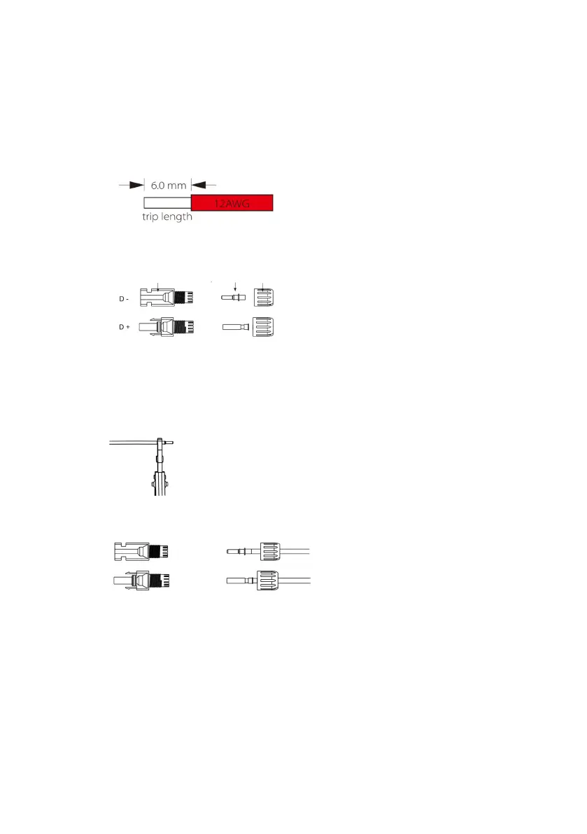
➢ Choose 12 AWG wire to connect the PV module.
➢ Trim 6mm of insulation from the wire end.
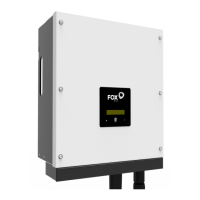
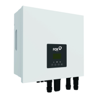
➢ Separate the DC connector as below.
Plug Pin contact Cable nut
➢ Insert striped cable into pin contact and ensure all conductor strands are captured in the pin contact.
➢ Crimp pin contact by using a crimping plier. Put the pin contact with striped cable into the corresponding
crimping pliers and crimp the contact.
➢ Insert pin contact through the cable nut to assemble into back of the male or female plug. When you feel or
hear a “click” the pin contact assembly is seated correctly.
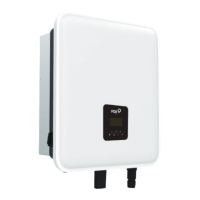
➢ Unlock the DC connector
- Use the specified wrench tool.
- When separating the DC+ connector, push the tool down from the top.
- When separating the DC - connector, push the tool down from the bottom.
- Separate the connectors by hand.
➢ Grid Connection
T series inverters are designed for three-phase grid. Voltage range is 220/230/240V; frequency is