FoxGate S6200 Series Installation Guide Chapter 1 Introduction
Table 1-1 FoxGate S6200 series port indications description
Panel Symbol Status Description
On (Green) The port is linked successfully
LED Status Description
On (Green)
The internal power is operating
normally
Power
Off Power is off or error
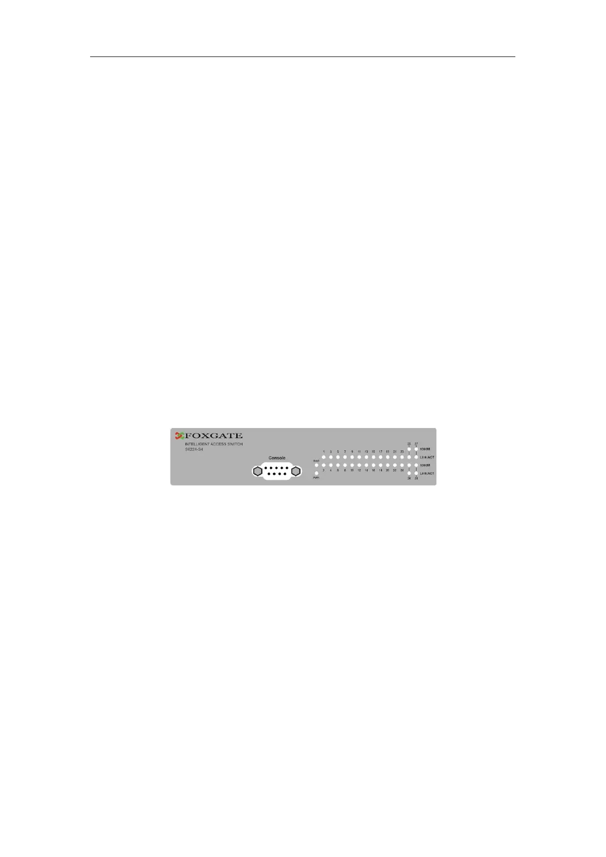
1.3.3.2 System Status Indicator Description
Fig 1-5 FoxGate S6200 series LED diagram
Table 1-2 FoxGate S6224-S4 system indicator description
Flash(Green)
The port is linked successfully, and
receive/send data
Port1-
24(Link/Act)
Off The port is not link
On (Green)
The port is linked successfully
Flash(Green)
The port is linked successfully, and
receive/send data
Port G1-G4
(Link/Act)
Off The port is not link
The port is in the link state of
100Mbps
On (Green)
Port1-
24(Speed)
The port is in the link state of 10Mbps
or at down status
Off
The port is in the link state of
1000Mbps
On (Green)
PortG1-
G4(Speed)
The port is in the link state of
10/100Mb
s or at down status
Off
5
 Loading...