4
CT-200
Under Sink Chiller Unit Installation Instructions and Use and Care Guide
LOCATION REQUIREMENTS
Determine where the chiller and all components being used in the installation should be mounted beforehand
and make sure there is adequate clearance for plumbing and electrical components and there is enough
tubing to reach the intended mounting positions. For best performance, position the chiller to allow a 2" (5 cm)
space around the top and sides. Do not put any objects on top of the chiller that could obstruct the fan.
ELECTRICAL REQUIREMENTS
A 120-volt, 60-Hz, 15- or 20-amp, grounded electrical supply is
required. It is recommended that a separate circuit serving only
your chiller unit be provided. Use an outlet that cannot be
turned on/off by a switch.
RECOMMENDED GROUND METHOD
The chiller must be grounded. This appliance is equipped with
a power supply cord with a 3 prong ground plug. To minimize
possible shock hazard, the cord must be plugged into a mating,
3 prong, ground-type outlet, grounded in accordance with all
national and local codes and ordinances. If a mating outlet is
not available, it is the personal responsibility and obligation
of the customer to have a properly grounded, 3 prong outlet
installed by a qualified electrician.
ELECTRICAL SHOCK HAZARD
Plug into a grounded 3 prong outlet.
Do not remove ground prong.
Do not use an adapter.
Failure to follow these instructions can
result in death, fire, or electrical shock.
WATER SUPPLY REQUIREMENTS
A cold water supply with a minimum pressure of 30 psi and a maximum pressure of 100 psi must be available
to the chiller. It can come directly from the water supply of the home, or from a water filtration system. A
Franke filtration system is highly recommended.
INSTALLATION INSTRUCTIONS
IMPORTANT: For subsequent steps, it will be required to cut and route tubing to fit the specific application in
your home. All tubing must be cut squarely and free of burrs. Ensure there is no damage within 1" of the cut end.
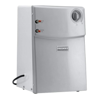
DO NOT USE ANY FORM OF SEALING
COMPOUNDS, this is not required for
push fit connections, and using sealing
compounds could cause leaks. All
tubing connections must be firmly
seated. Tubing must be routed to avoid
sharp bends and have enough slack to
avoid straining connections. A P-clip
and mounting screw is included to
hold the tubing in place as needed.
Pull gently on each connection to
make sure they are secure. See
Diagram 1 for details on tubing
installation and removal.
HOW TO INSERT/REMOVE TUBING
IN PUSH FIT CONNECTIONS
DIAGRAM 1