1.
2.
3.
4.
5.
6.
7.
8.
9.
10.
11.
12.
13.
14.
15.
16.
13.
5
CT-200
Under Sink Chiller Unit Installation Instructions and Use and Care Guide
INSTALLATION INSTRUCTIONS
The following instructions pertain to the connection of this chiller to a Franke filtration system and Franke Little
Butler
®
series dispensing faucets. The connection options for all compatible Franke products will be reviewed
in this document. Make sure you understand which connection option applies to your specific installation.
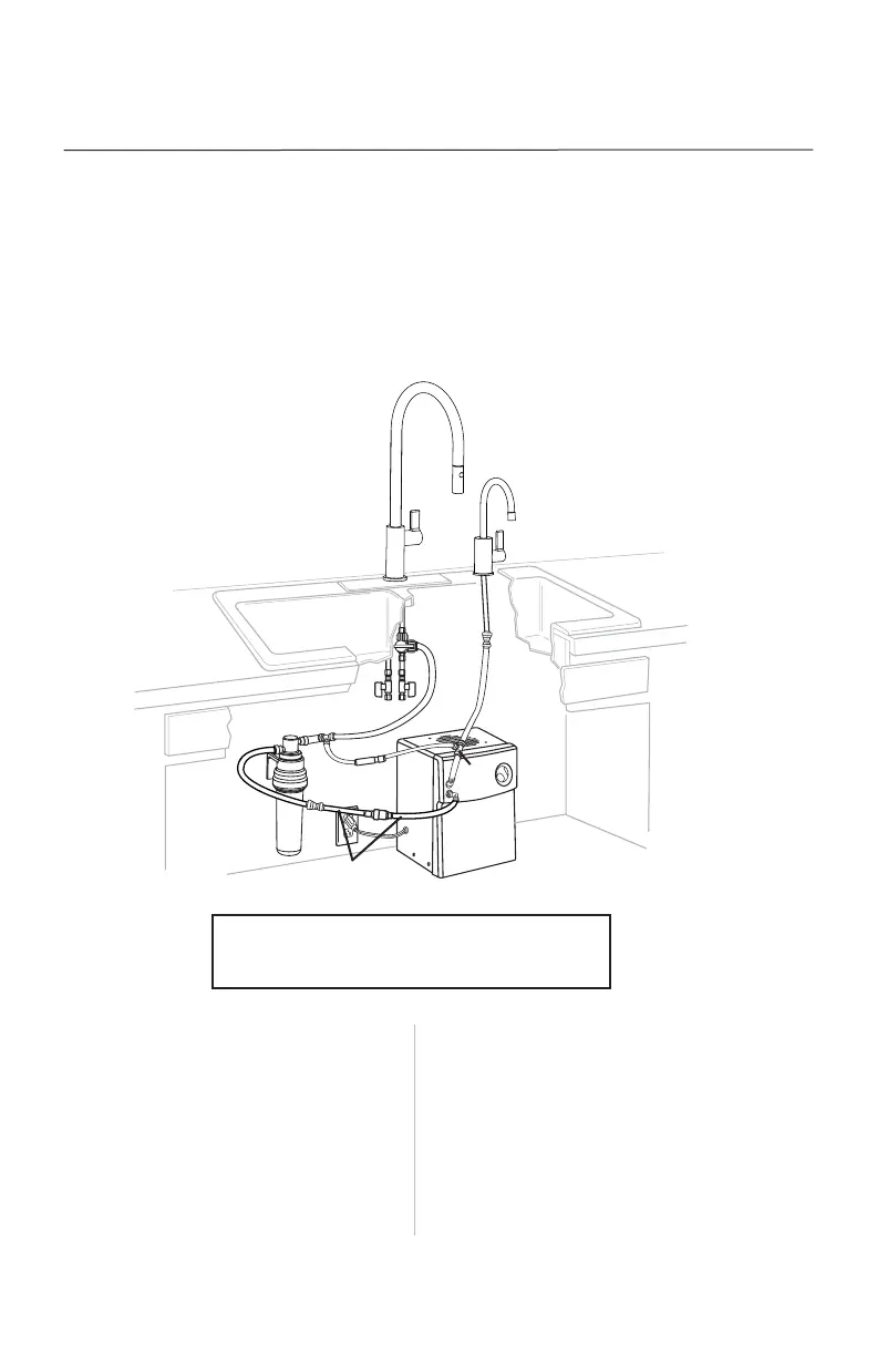
Diagram 2 illustrates a general overview of the entire installation for ALL COLD ONLY Little Butler
®
dispensing faucets.
1. Chiller unit
2. 1/4" tee push fitting
3. 1/4" blue tubing
4. Franke Little Butler
®
cold only faucet
(sold separately)
5. Cold water supply from home
6. Hot water supply from home
7. 1/4" white tubing
8. Franke filtration system (sold separately)
9. 10306 shut-off valve (sold separately)
10. 3/8" x 3/8" x 1/4" push fitting
11. Check valve
12. 3/8" tubing
13. 3/8"-1/4" reducer push fitting or 1/4"
compression fitting (not shown)
14. SB60 pressure safety valve (sold separately)
15. 1/4" elbow push fitting
16. Franke kitchen faucet (sold separately)
DIAGRAM 2:
COLD ONLY LITTLE BUTLER DISPENSING FAUCET
12.
12.
7.