180
90
d2
d1
Installation and technical data
Page 16
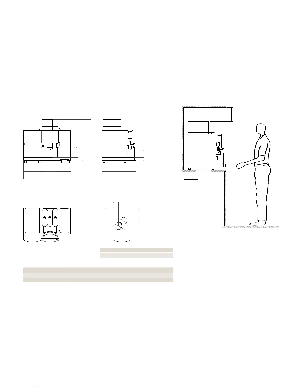
40 mm 520 mm + 40 mm = 560 mm
70 mm 520 mm + 70 mm = 590 mm
100 mm 520 mm + 100 mm = 620 mm
d1 Hole for cables and feed lines 120 mm
d2 Hole for coffee ground chute 120 mm
Adjustable feet (optional)
Cross-section from above (Buffet feed-through)Top view
Side viewFront view
The dimensions are specified in mm.
Prepare a stable, ergonomic surface (min. load capacity: 150 kg
or 330.7 lb). The operator panel should be at eye level.
Distance to the wall must be at least 50 mm. Clearance above the
machine must be at least 200 mm.
Adjustable feet (optional) can be used to compensate for uneven-
ness or height differences.
If optional add-on units are installed, up to an additional 300 mm
may be required per add-on unit.
Observe the connection requirements of the add-on units.
Installation dimensions of the FM850Dimensions of the FM850