6
HT-300
Under Sink Heating Tank Installation Instructions and Use and Care Guide
Step 1 – Install “open vent” dispensing faucet per faucet instructions. For fresher tasting water, a Franke
fi ltration system can be used with the Heating Tank as long as water pressure to the heating tank does not
drop below 20 psi. This will be connected in line ahead of the dispensing faucet as illustrated in Diagram1.
Step 2 – Mount heating tank in cabinet underneath the sink in desired location. There are holes in the back
of the tank for easy mounting to the wall using screws (not provided).
Step 3 – Connect dispensing faucet to heating tank.
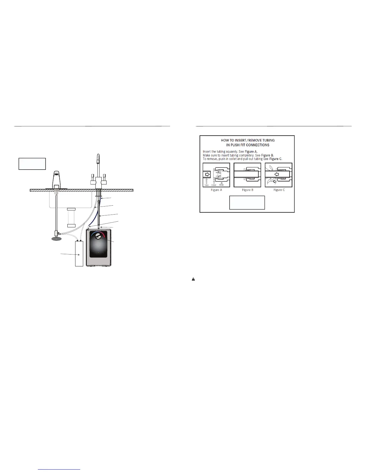
• Connect ¼” push fi tting included with the tank to the water inlet near the back corner of the heating
tank
• Connect heating tank supply tubing from the dispensing faucet to the push fi tting at the water inlet of the
heating tank
• For push fi ttings, do not use any form of sealing compounds, this is not required for push fi t connections,
and using sealing compounds could cause leaks. All tubing connections must be fi rmly seated. Tubing
must be routed to avoid sharp bends and have enough slack to avoid straining connections. See
Diagram 2 for details on tubing installation and removal.
Tank must be
mounted vertically
BE SURE DIAL IS IN OFF OR MIN
POSITION DURING INSTALLATION
Heating tank supply tube (back corner of tank)
Cold water supply tube
Clear silicone return tube (center of tank)
Connector Reducer Adapter
Optional Water Filter
Water Sink
Kitchen Faucet Hot Water Dispensing Faucet
Drain Pipe
1/4” Push Fitting Connector
HT-300
MIN
MAX
INSTALLATION INSTRUCTIONS
The following instructions pertain to the connection of this heating tank to Franke Little Butler® series
dispensing faucets and optional Franke fi ltration systems. Diagram 1, below is for visual reference of the
installation steps.
DIAGRAM 1
7
HT-300
Under Sink Heating Tank Installation Instructions and Use and Care Guide
• Connect silicone heating tank return tubing from the dispensing faucet to the center outlet on top of the
tank using the connector/reducer adapter and the hose clamp included with the heating tank.
• Silicone tubing can also be cut to length so there are no unnecessary loops or twists or kinks.
Step 4 – Turn on water supply and open hot valve in dispensing faucet to fi ll tank (about 1 minute). When
tank is full, water will fl ow from the dispensing faucet. Inspect for leaks while faucet is running and after
turning faucet off .
Step 5 – Prepare for Power
Double check the thermostat control dial is in the OFF position. Thermostat control dial controls the water
temperature, not the water fl ow or delivery.
This dispenser is equipped with a self re-setting thermal fuse.
Turn the thermostat to OFF position and fi ll tank with water before plugging the power cord from the tank
into an electrical outlet.
If tank is empty and the thermostat set in the ON position when the power cord is connected, the self
re-setting fuse in the heater control will disconnect the current to the heater after approximately one min-
ute, thus protecting the heater from a “dry start” failure. The fuse in the heater control will self-reset after
approximately 1/2 hour. Turn on the water supply to the tank and continue the installation.
Continued misuse will cause damage to the appliance and is detectable thus, voiding the warranty.
Step 6 - Test Installation
Plug electrical cord into a grounded 3-prong outlet. Do not use an outlet controlled by an off /on wall switch.
Turn thermostat control dial clockwise to the highest position. Maximum temperature will be reached in
about 15 minutes and dispenser will be ready for use. Lower the temperature setting by turning thermostat
control dial counterclockwise if you notice vapor or a boiling noise. To raise or lower the water temperature,
rotate the thermostat dial. At the LOW setting of thermostat dial water temperature will be approximately
140°F (60˚C) ±5°and the HIGH setting of the thermostat dial water temperature will be approximately
200°F (93°C) ±5°.
DIAGRAM 2
WARNING

 Loading...