Operation
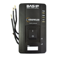
A. Manual operation
The rotary switch of the electric motor starter can
be used to switch the pump/motor on and off. To
maintain the IP rating of the control box, close
the control box lid after every manual switching
operation. The SubTronic3P
®
provides you with a
complete protection system for your water pump.
To make optimal use of the SubTronic3P
®
operating
capabilities, observe the Indicators and consult the
Trouble Shooting Section in this manual.
If a repeated overload condition is
experienced, contact your installer or
service provider.
B. Automatic operation - pressure switch
$ÀRDWSUHVVXUHRUDQ\RWKHUH[WHUQDOVZLWFKcan
be used to power the SubTronic3P
®
. Remember to
leave the ON/OFF switch in the SubTronic3P
®
in
the ON position if an external control switch is used.
Required external switch contact rating: 400V/1A
unipolar.
Managing ON/OFF switching activity
Your submersible electric motor accumulates a
certain amount of heat each time it is switched on. It
must run for a period of time during which it has the
opportunity to dissipate the heat. If too many starting
cycles are called for your motor and/or pump may
be damaged. Observe the starting conditions of the
motor/pump. The SubTronic3P
®
will interrupt ope-
ration if the motor or pump life is threatened. Check
the Trouble Shooting Section in this manual to rectify
the problem or contact your authorized installer or
service provider.
Life threatening voltage
Make sure that nobody can switch
on the power unexpectedly while
work is being carried out.
Make sure that multiple earth-points
are avoided. Refer to the local
standards and norms for borehole
installations
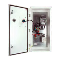
Installation Procedure
Installation - Mechanical
Your control box comes supplied with an external
PRXQWLQJRSWLRQ7KHGLDJUDP6HH¿JXUH%VKRZV
a rear view of the control box, indicating mounting
dimensions.
7KHFRQWUROER[VKRXOGEHPRXQWHGRQDYHUWLFDOÀDW
surface.
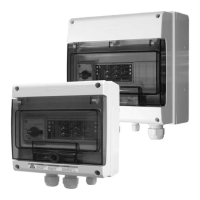
Installation - Electrical
Any electrical system such as described in this
manual must only be installed by professional staff
TXDOL¿HGHOHFWULFDOWHFKQLFLDQ
&RQ¿UPWKDWWKHFRQWUROER[FXUUHQW
rating corresponds with the motor
VSHFL¿FDWLRQ
Avoid mounting the equipment in
GLUHFWVXQOLJKWQHDURSHQÀDPHVRULQ
the line of pressurized water or other
liquids. Take the necessary environ-
mental conditions into consideration.
6HH¿JXUH$IRUWKHZLULQJGLDJUDP$OOFRQQHFWLRQV
must be checked if the installation was not commissi-
oned by you.
1. TURN OFF AC POWER AT THE SOURCE
',675,%87,21%2$5'AND MAKE SURE IT
CANNOT BE ACCIDENTALLY SWITCHED ON
WHILE WORK IS BEING CARRIED OUT.
2. Remove the enclosure lid.
3. Connect the incoming 400V AC supply to the
control box as shown in the wiring diagram.
)LJXUH$
4. Connect the motor to the control box.
5. Remove strap from auxiliary switch terminals
to connect external switch lead. If no auxiliary
switch is used, leave strap in, tap the unused
cable gland using a suitable plug to maintain IP
rating and skip to next point.
6. Tighten all screw terminals
7. Replace the enclosure lid and tighten screws
8. TURN ON AC POWER AT THE SOURCE (DIS-
75,%87,21%2$5'
4 GB
Underload Smart Reset
If a motor Underload fault condition occurs, the most
likely cause is an overpumped or dry well. To allow
the well to recover, the SubTronic3P
®
controller will
wait 5 minutes to 60 minutes, determined by duration
of the previous run time, before restarting the motor.
)RUH[DPSOHWKH¿UVWWLPHWKHIDXOWRFFXUVWKH
controller will wait circa 5 minutes before attempting
to restart the pump. If the system would then run for
less than 3 minutes and an Underload fault recurs,
the controller will wait approx. 10 minutes before at-
tempting to restart the pump. This schedule allows for
the minimum off-time possible based on the recovery
time of the well. See page 5: Figure 1
INFORMATION!
INFORMATION!
INFORMATION!
DANGER!
Electrical wiring diagram
DANGER!
 Loading...