TGA100 Rev0106
23
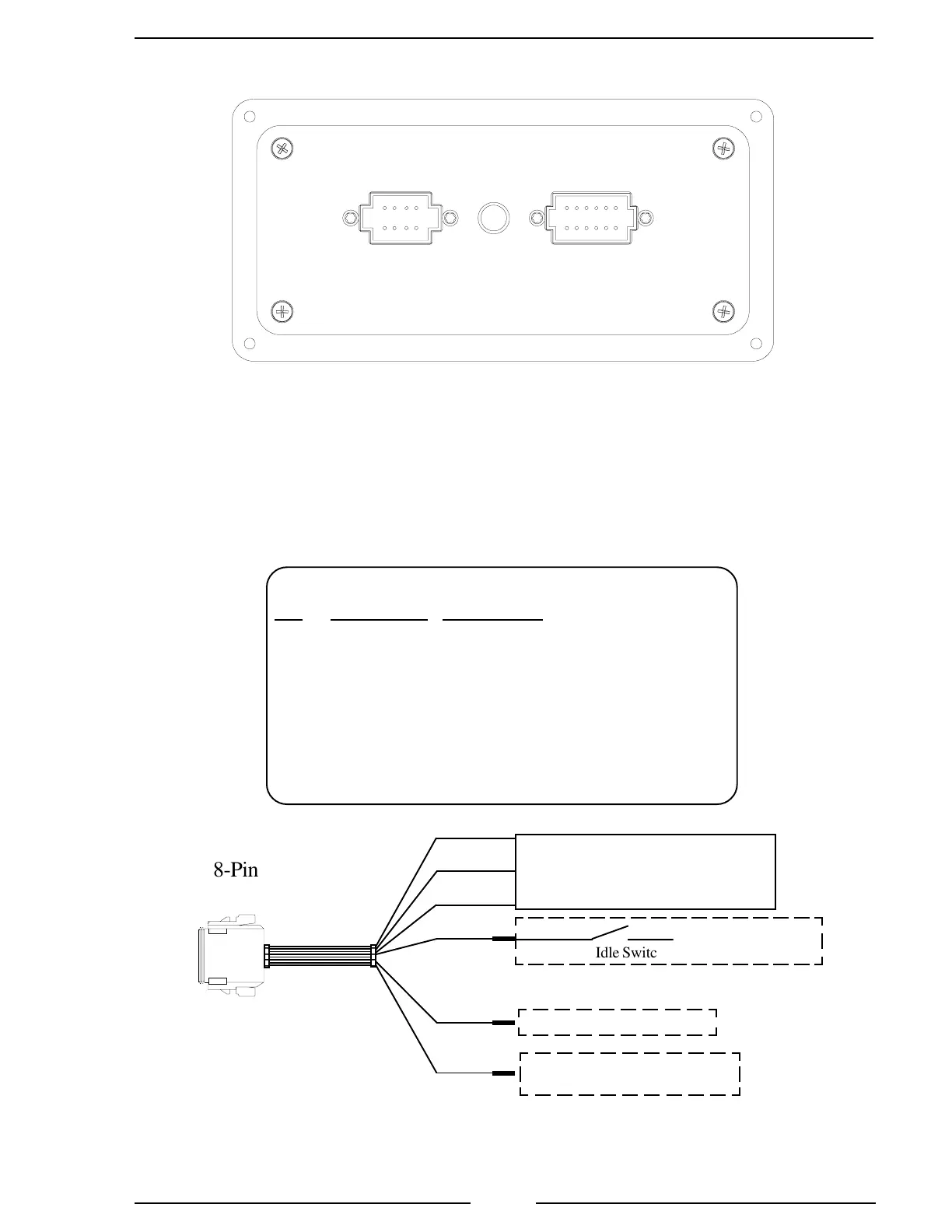
Figure 5. TGA 8-Pin Connector Wiring
8 Pin Connector/Cable
Pin Wire Color Description
1 Red +5 VDC Reference From ECM
2 Black ECM Ground
3 White Engine Control Signal To ECM
4 White High Idle Active Input (Ground)
5 N/C N/C
6 N/C N/C
7 Black Buzzer Ground
8 Blue Transmission Temp. Sensor
RED
BLK
WHT
WHT
BLK
BLU
8-Pin
Connector
3-Wire Cable
To Engine Control
(See Engine Specific Wiring)
Refer to High Idle
Wiring for details.
8-Pin Cable
High Idle Switch
To Ground Side of Buzzer
To Transmission Temperature
Sensor TGA200 only
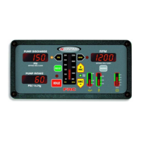
Rear View
8 and 12-Pin Connectors
 Loading...