Do you have a question about the FRC PumpBoss PBA100 and is the answer not in the manual?
Describes the PumpBoss governor's dual modes (pressure/RPM) and core functionality.
Lists key features like J1939 CAN bus, programmable presets, and diagnostic capabilities.
Covers display module, LED bar graphs, engine sensor ranges, and pressure sensor details.
Lists compatible engine models (Cummins, Detroit Diesel, Ford, etc.) with their corresponding PBA numbers.
Lists the key components of the PumpBoss system, including control module, sensors, and cables.
Describes the pressure sensor mounting and connection.
Details installation of engine coolant and oil pressure sensors.
Covers optional audible alarm buzzer and transmission temperature sensor.
Describes the 8-pin and 12-pin cables for interface connections.
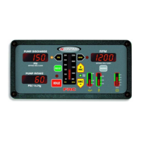
Explains Oil Pressure, Temperature, RPM, Battery Voltage LEDs, and Message Display.
Describes Silence, Preset, Idle, Mode, and Menu buttons.
Explains the control knob operation, RPM/PSI LEDs, and MODE button.
Describes the Day/Night Sensor and MENU button functions.
Steps for mounting the control module, including panel cutout and screw holes.
Details the procedure for mounting and connecting the pressure sensor to the pump manifold.
Explains how to install engine sensors for RPM, oil pressure, and coolant temperature.
Covers the installation of the optional buzzer and high idle kit.
Details the operation of the Control Knob, MODE, MENU, SILENCE, and PRESET buttons.
Explains how to operate the PumpBoss in pressure mode and manage discharge valves.
Describes how the PumpBoss handles situations with no or low water supply.
Explains how to operate the PumpBoss in RPM mode and its pressure limiting feature.
Details how to switch between pressure and RPM modes smoothly.
Explains how to manage high discharge pressure when the engine is at idle.
Describes how to set and change pre-programmed pressure or RPM values.
Explains the high idle function and how to change its setting.
Details how to access and view stored accumulated hours and transmission temperature.
Explains how fault warnings are stored and retrieved.
Describes how the maximum engine RPM is stored and displayed.
Step-by-step guide to entering the four-digit program code.
Lists and explains various program codes for data display and parameter settings.
Details the 12-pin Deutsch connector, 12-pin cable, and its wire assignments.
Shows the 8-pin cable and connector wiring, including pin assignments for controls and power.
Illustrates the wiring for the pressure sensor, including the 3-pin connector.
Explains the typical 9-pin Deutsch diagnostic connector used in vehicles.
Explains the wiring diagram for the high idle function, including switches and diodes.
Details wiring for Cummins ISB, ISC, ISL, and ISM engines, referencing J1939 datalink.
Details wiring for Detroit Diesel DDEC VI and DDEC IV/V engines.
Explains Navistar engine connections, including J1939 datalink and RESCM.
Details Caterpillar engine connections, including J1939 datalink and PTO switches.
Provides wiring for Ford engines, including adapter assemblies and RPM signal levels.
Explains the torque lock-up module wiring for automatic transmissions.
Details Scania engine connections for P, R, and T-series trucks with BWS.
Explains wiring requirements for GMC engines using an adapter and cable assembly.
Details wiring for 2007 Mercedes engines, including J1939 and VCU connections.
Provides wiring details for Mercedes ACTROS models, focusing on remote throttle.
Describes typical circuits showing flyback diode installation across inductive loads.
| Brand | FRC |
|---|---|
| Model | PumpBoss PBA100 |
| Category | Controller |
| Language | English |