TGA100 Rev0106
29
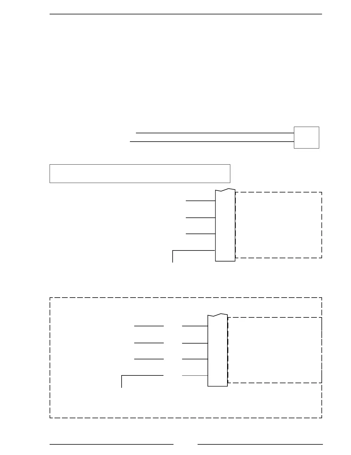
Figure 10. Navistar TGA104/204 Wiring
Navistar Harness Connections
Interface Information
The ECM must be programmed for a remote throttle input. Set PTO REMOTE
PEDAL to 1. (This will enable the remote throttle input.)
The VARIABLE PTO ENABLE input has to be at 12 VDC to activate the
remote throttle. (12 VDC can be picked up from the interlock circuit.)
12-Pin
Connector
(Refer to
Figure 4)
9-Pin
Deutsch
Connector
ATA (–)
Black Wire
Red Wire
Pin G
ATA (+)
Pin F
8-Pin
Connector
(Refer to
Figure 5)
REMOTE THROTTLE INPUT
RESCM
VARIABLE PTO ENABLE
+5VDC REFERENCE
REMOTE THROTTLE
GROUND
11
19
14
17
White Wire
Black Wire
Red Wire
Note: Supply +12 when
the pump interlock
circuit is engaged.
J3 (blue)
Connector
Note: 2004 and newer model engines with code 12VXY and
the Remote Engine Speed Controller Module (RESCM) installed.
8-Pin
Connector
(Refer to
Figure 5)
99F
97DD
97HM
97CC
REMOTE THROTTLE INPUT
NAVPAK ECM
VARIABLE PTO ENABLE
+5VDC REFERENCE
REMOTE THROTTLE
GROUND
5
36
6
30
White Wire
Black Wire
Red Wire
Note: Supply +12 when
the pump interlock
circuit is engaged.
Older Model Engines
Check ECM Connector
J1587 Datalink
J1587 Datalink
 Loading...