TGA100 Rev0106
27
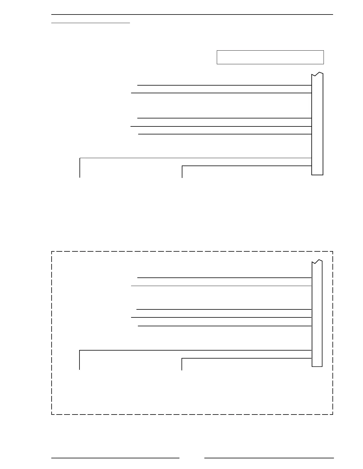
ISM Engine Interface
Figure 8. Cummins TGA101/201 Wiring
(Sheet 2 of 2)
ECM 50-Pin
J2 Connector
J1587 Datalink (–)
12-Pin
Connector
(Refer to
Figure 4)
Black Wire
J1587 Datalink (+)
20
10
32
21
26
03
14
ECM Return (Sensor)
8-Pin
Connector
(Refer to
Figure 5)
Remote Accelerator Position
Sensor Supply
Red Wire
Black Wire
White Wire
Max Operating Speed/Governor Type Switch
Remote Accelerator On/Off Switch
Note: Supply a
ground when the
pump interlock
circuit is engaged.
Note: Supply a ground when the pump
interlock circuit is engaged.
This assumes that the ECM is set
with Automotive governor as the
default mode.
Red Wire
ISM02-CM870 Model Engines
ECM 50-Pin
C1 Connector
J1587 DATALINK (–)
J1587 DATALINK (+)
12-Pin
Connector
(Refer to
Figure 4)
Black Wire
Red Wire
27
26
49
48
21
43
25
ACCELERATOR SUPPLY RETURN
8-Pin
Connector
(Refer to
Figure 5)
REMOTE ACCELERATOR POSITION
ACCELERATOR SUPPLY (+)
Black Wire
Red Wire
White Wire
ACCELERATOR GOVERNOR SWITCH
REMOTE ACCELERATOR SWITCH
Note: Supply a ground fwhen the pump
interlock circuit is engaged.
This assumes that the ECM is set
with Automotive governor as the
default mode.
Note: Supply a
ground when the
pump interlock
circuit is engaged.
Older Model Engines Check ECM Connector
 Loading...