TGA100 Rev0106
3
List of Tables
Table 1. Pressure Sensor Output Voltage .................................................................. 5
Table 2. Engine Type Setting ................................................................................... 19
Table 3. Fault Codes................................................................................................ 21
List of Figures
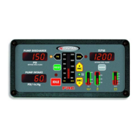
Figure 1. Controls and Indicators .............................................................................. 9
Figure 2. Control Panel Mounting Dimensions ........................................................ 10
Figure 3. Pressure Sensors ...................................................................................... 11
Figure 4. TGA 12-Pin Connector Wiring ................................................................. 22
Figure 5. TGA 8-Pin Connector Wiring................................................................... 23
Figure 6. Pressure Sensor Wiring ............................................................................ 24
Figure 7. Common OEM Connectors ..................................................................... 25
Figure 8. Cummins TGA101/201 Wiring ................................................................. 26
Figure 9. Detroit Diesel (Series 50 and 60) TGA102/202 Wiring............................. 28
Figure 10. Navistar TGA104/204 Wiring ................................................................. 29
Figure 11. Caterpillar TGA105/205 Wiring .............................................................. 30
Figure 12. Mercedes TGA110/210 Wiring ............................................................... 33
Figure 13. High Idle Wiring...................................................................................... 34
Figure 14. Flyback Diode ........................................................................................ 35
 Loading...