©2008
TT 9.0 / 722.30822
P. 7
4
3
16
= (1)
= (1)
= (4)
13
17
= (6)
= (6)
= (1)
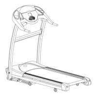
FIGURE 1
22
= (2)
1
= (1)
A5
A5
22
22
Français
FIGURE 1: ASSEMBLAGE DES MONTANTS DU TABLEAU DE
COMMANDE
• Fixer le montant droit (n° 3) et gauche (n° 4) au bâti principal en utilisant
deux boulons (n° 16), deux rondelles à ressort (n° 13) et deux rondelles
(n° 17) au côté de chaque montant.
• Fixer le devant de chaque montant à l’aide d’un boulon (n° 22), une
rondelle à ressort (n° 13) et une rondelle (n° 17).
• Connecterensemble deux pièces de câble de console pour qu’ils se
joignent ensemble fermement.
(Page suivante)
English
FIGURE 1: CONSOLE MAST TUBE ASSEMBLY
• Attach the Console Mast Tube - Right (#3) and Left (#4) to the Main
Frame Assembly using two Bolts (#16), two Spring Washers (#13),
and two Washers (#17) at the side of each Console Mast Tube.
• Attachthefrontofeach Console Mast Tube using one Bolt (#22),
one Spring Washer (#13), and one Washers (#17).
• Connecttwopiecesofconsolecablessotheyttogethertightly.
(Continued on the next page.)