©2008
TT 9.0 / 722.30822
P. 8
FIGURE 2
FIGURE 2A
6
5
= (1)
= (1)
18
= (4)
= (1)
A5
5
6
A5
5
6
18
18
18
Français
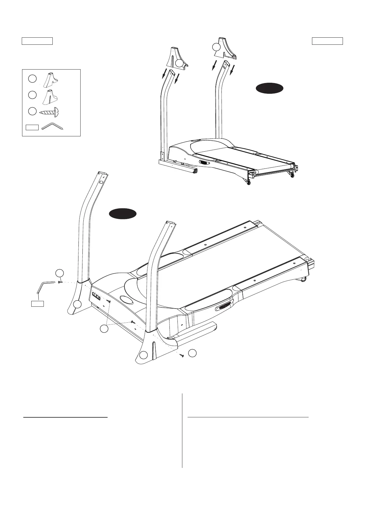
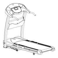
FIGURE 2: ASSEMBLAGE DES PIEDS DES MONTANTS
• Insérer le pied du montant gauche (n° 6) et le pied droit (n° 5) en les
faisant glisser sur les montants du tableau de commande. Insérer les
pieds jusqu’à la base des tubes. NOTA: Ne tirez pas le câble par
l’ouverture avant que le pied du montant ne soit placé sur le montant.
• Fixer les pieds du montant gauche aux montants du tableau de
commande. Utiliser deux vis (n° 18) par pied du montant.
(Page suivante)
English
FIGURE 2: MAST BOOT ASSEMBLY
• Slide the Mast Boot - Left (#6) and Right (#5) down the Console
Mast Tubes to the bases. NOTE: Do not pull the cable through the
opening until the mast boot is placed on the mast.
• Attach the Mast Boots to the Console Mast Tubes using two Screws
(#18) per Mast Boot.
(Continued on the next page.)