©2008
TT 9.0 / 722.30822
P. 9
2
21
A5
A5
9
21
9
3
FIGURE 3
FIGURE 3C
FIGURE 3A
FIGURE 3B
8
7
= (1) = (2)
1514
= (4) = (6)
20
19
= (2)
= (4) = (1)
9
= (1)
21
= (7) = (1) = (1)
A5
= (1)
A4 A6 A7
2
= (1)
A4
A7
A4
FIGURE 3D
A5
A6
23
23
= (1)
Français
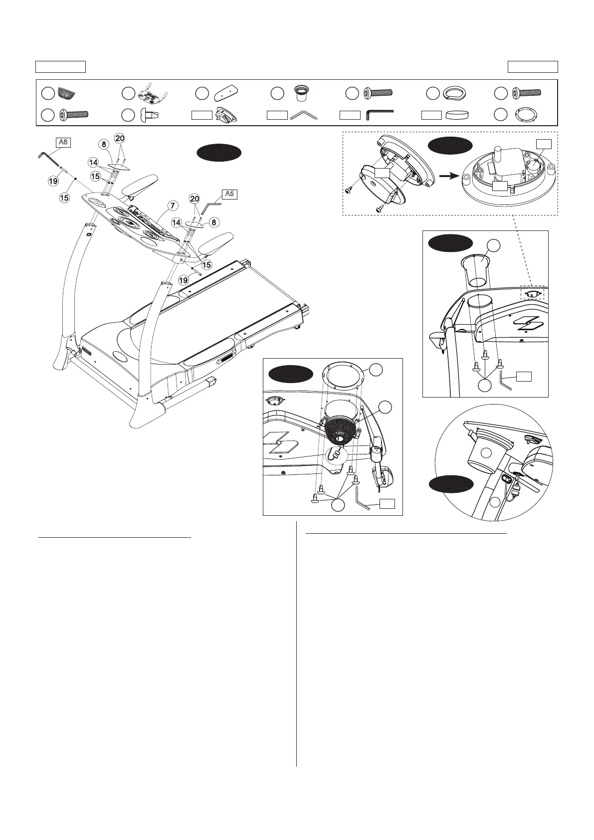
FIGURE 3: ASSEMBLAGE DU TABLEAU DE COMMANDE
• Mettreletableaudecommande(n°7)surlesmontantsdutableaude
commande. Fixer-le du sommet à l’aide de quatre boulons (n° 14) et
quatrerondelles(n°15),etxer-ledescôtésàl’aidededeuxboulons
(n°19) et deux rondelles (n° 15). Utiliser la clé Allen (n° A6).
• Relierlesdeuxplaquesdutableaudecommande(n°8)autableaude
commande (n° 7) en utilisant deux boulons (n° 20) par plaque. Se servir
de la clé Allen (n°A5) pour serrer les vis.
• Insérerleporte-bouteille(n°9)dansletableaudecommande(n°7)etle
xeràl’aidedetroisvis(n°21),commelemontrelagure3A.
• Enleverl’anneaudeventilateur(n°23)duventilateur(n°2)etl’insérer
dans le tableau de commande, comme illustré. Fixer-le à l’aide de quatre
vis(n°22).Voirlagure3C.
• Relierleslsderaccordement,commelemontrelagure3D.
NOTA : Pousser doucement les connecteurs dans l’ouverture du tube.
• Retirerlesdeuxvisdel’arrièreduboîtierdelaminuterie (n°A4) etle
protecteur,commelemontrerlagure3B.Insérerlapilebouton(n°A7)
dans la minuterie. NOTA : S’assurer que la pile est bien orientée.
• Refermer le boîtier de la minuterie (n°A4) et serrer les vis ayant été
retirées. NOTA: Régler l’heure à l’aide de la roulette située à l’arrière de
la minuterie.
(Page suivante)
English
FIGURE 3: CONTROL PANEL ASSEMBLY
• PlacetheControlPanelAssembly(#7)ontotheConsoleMastTubes.
Attach from the top using four Bolts (#14) and four Washers (#15),
and attach from the sides using two Bolts (#19) and two Washers
(#15). Use the Allen Key (#A6).
• Now connect two Console Plates (#8) to the Control Panel Assembly
(#7) using two Bolts (#20) per Plate. Use the Allen Key (#A5) to
tighten.
• Insert the Cup Holder (#9) into the Control Panel Assembly (#7) using
three Screws (#21), as shown in Fig. 3A.
• Remove the Fan Ring (#23) from the Fan (#2) and insert into the
console as shown. Attach using four Screws (#21).Connect two
piecesofFanWiressotheyttogethertightly.SeeFig.3C.
• Connect two pieces of Console Cables, as shown in Fig. 3D.
NOTE: Gently push the connectors into the tube opening.
• Remove the two Screws from the rear housing of the Clock Assembly
(#A4) and remove cover, as shown in Fig. 3B. Insert Button Battery
(#A7) into the Clock Assembly. NOTE: Check for proper battery
orientation.
• Close the Clock Assembly (#A4) and re-insert the previously-removed
screws. NOTE: Set the time using the control wheel on the back of
the Clock Assembly.
(Continued on the next page.)