2201 Cantu Court Suite 215 Sarasota, FL 34232 Page 14 of 23
(941) 378-4242 (800-237-3928 Fax (941) 378-2765
Stewartsigns.com
Installing the Transceivers
Included in the Transceiver box is the following:
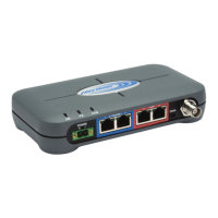
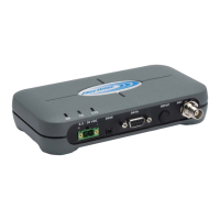
a. 2 ea. RF Transceivers installed in a Metal Enclosure.
b. 1 set of Antenna adapters
c. 1 Antenna Extension cable (to be used inside the sign).
d. 1 Bulkhead Connector.
e. 2 ea. Antennas
f. 2 ea. power adapters
g. 1 ea. cable with RJ45 connector on one end and a 6 pin Panduit on the
other end.
h. 1 ea. 6 Ft. length Ethernet cable
i. Plastic Mounting Shoe.
Connecting your Transceiver to the CPU board in the Sign
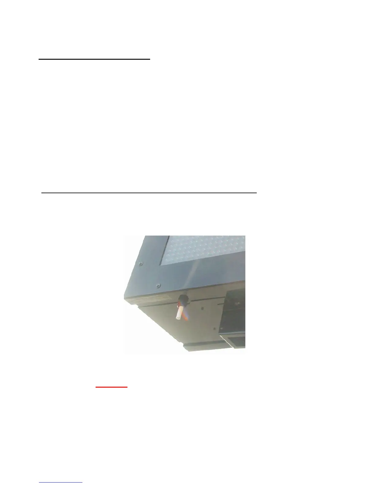
1. One Transceiver will be installed inside ID cabinet #1 of the sign. ID cabinet #1 is
identified by the temperature probe mounted at the lower left corner of the LED
cabinet. Figure #19
Figure #19 The Temp Probe is Located at the Bottom Left of ID# 1
NOTE: To Avoid electrical shock be sure and Install the Transceiver in the Sign
BEFORE you plug in the Power Adapter.