2201 Cantu Court Suite 215 Sarasota, FL 34232 Page 17 of 23
(941) 378-4242 (800-237-3928 Fax (941) 378-2765
Stewartsigns.com
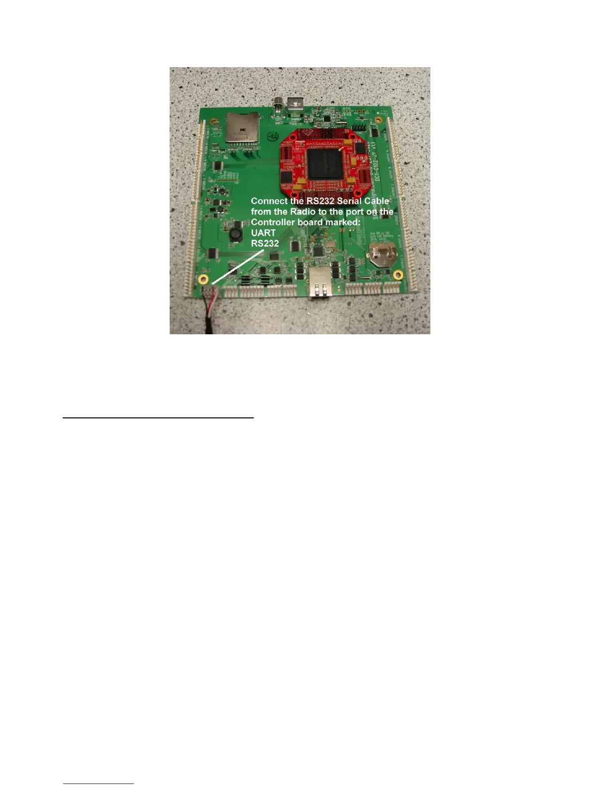
Figure #21a New CPU Board inside the Sign
Mounting the External Antenna
1. Drill a 5/8” hole in ID#1 side of LED cabinet 9 inches below the top of the LED cabinet to
accommodate the bulkhead connector. Be careful not to interfere with the light Sensor
mounted inside the cabinet. See figure #22
2. Mount the bulkhead connector in the hole you drilled in step#1. The “O” ring goes on the
outside of the cabinet. The lock washer and retaining nut goes on the outside of the
cabinet. See figure #23.