DANGER
Read and follow all applicable warnings and in-
structions in the applicable brake chamber section
in Group 42 of the
Business Class
®
Trucks Ser-
vice Manual
for repairs to the service/parking
brake chambers. These chambers contain a power
spring, which if released, could cause serious in-
jury or death.
4.2 If leakage is detected at either the clamp
ring or the drain slots, replace the parking
brake section. Slight leakage is permitted
at the service port. Any other leakage is
not acceptable. Using the instructions in
the applicable brake chamber section in
Group 42 of the
Business Class
®
Trucks
Service Manual
, replace the parking
brake section (
do not attempt to service
the parking brake section
).
5. Connect the air hose to the brake chamber, mak-
ing sure that the fittings are clean and free of
debris. Tighten the nut finger-tight. Using a
wrench, further tighten the nut until you feel re-
sistance. Then, tighten the nut one-sixth turn
more.
6. Repeat the above steps for each parking brake
chamber.
7. Apply the parking brakes. Remove the chocks
from the tires.
42–08 Air Dryer Desiccant
Replacing, Meritor
WABCO System Saver
1000
Replace the desiccant cartridge. For instructions, see
Group 42 of the
Business Class
®
Trucks Service
Manual
.
NOTE: Desiccant change intervals may vary
from vehicle to vehicle. Typical desiccant car-
tridge life is three years. However, if experience
has shown that extended or shortened life has
resulted on a particular installation, then the in-
terval can be increased or decreased accord-
ingly.
42–09 Meritor Brake Adjusting,
Manual Slack Adjusters
Meritor
1. Check the adjustment on Meritor brakes when-
ever the brake chamber piston rod applied stroke
exceeds the maximum allowable stroke.
1.1 With the brakes released, measure the
distance from the face of the brake cham-
ber to the centerline of the clevis pin
(Fig. 4, Ref. A). Record the exact dis-
tance as measurement A.
1.2 Apply the service brakes and hold them
on full line pressure of at least 80 psi
(550 kPa). Measure the distance from the
face of the brake chamber to the center-
line of the clevis pin (Fig. 4, Ref. B).
Record the exact distance measured as
measurement B.
1.3 Subtract measurement A from measure-
ment B to determine the applied stroke.
2. If the applied stroke equals or exceeds the maxi-
mum allowable stroke, adjust the brakes. See
Table 3.
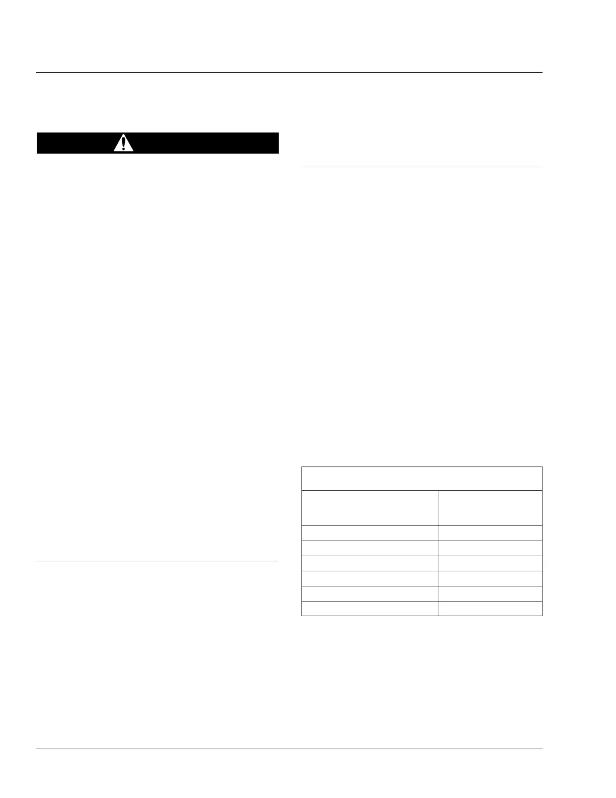
Maximum Allowable Brake Chamber Stroke, with
Meritor Manual Slack Adjusters
Chamber Size Effective Area:
square inches
Maximum Allowable
Stroke:
*
inches (mm)
(B minus A)
12 1-1/2 (38)
16 1-3/4 (44)
20 1-3/4 (44)
24 1-3/4 (44)
24 (long stroke) 2 (51)
30 2 (51)
*
Adjust the brakes whenever the applied stroke exceeds the maximum.
Table 3, Maximum Allowable Brake Chamber Stroke,
with Meritor Manual Slack Adjusters
2.1 Wipe clean the adjusting screw hexhead.
See Fig. 4. Position a wrench or socket
over the adjusting screw hexhead.
Brakes42
Business Class Trucks Maintenance Manual, October 199842/6