3.3 If the free-stroke is incorrect, remove the
pressure-relief capscrew, gasket, pawl
spring, and pawl (Fig. 6, Ref. 5) from the
slack adjuster housing. If equipped with a
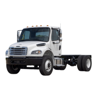
pull-pawl assembly (Fig. 8), carefully in-
sert a screwdriver and raise the relief cap
about 1/8 inch (3.2 mm).
CAUTION
Before turning the adjusting nut, remove the
pressure-relief capscrew, gasket, pawl spring, and
pawl. If equipped with a pull-pawl assembly, raise
the relief cap as instructed. Failure to do so could
strip the teeth on the pawl.
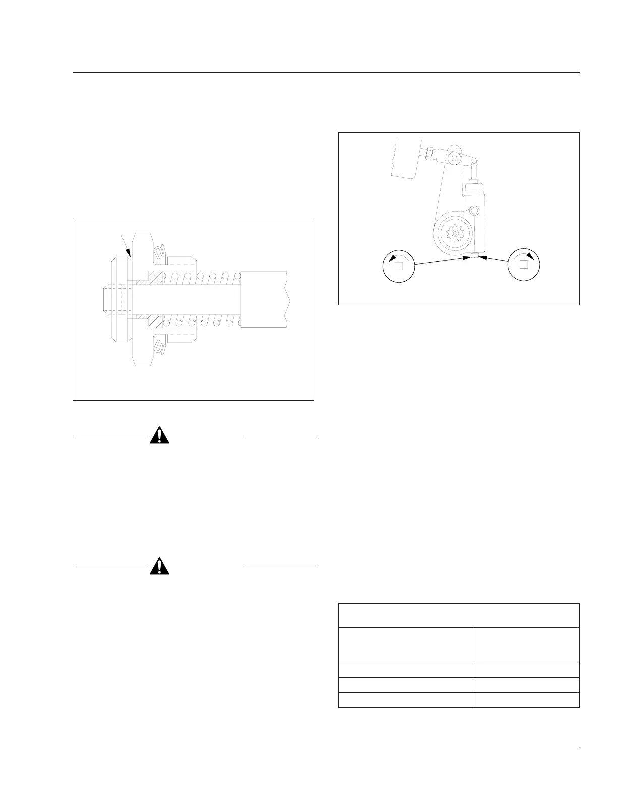
3.4 Turn the adjusting nut one-eighth turn, as
shown in Fig. 9. Measure the stroke
again, and adjust until correct.
CAUTION
Do not make the adjusted chamber stroke too
short. The free-stroke must not be less than the
measurements given previously. If the chamber
stroke is too short, the linings can drag, which
could damage the brake.
3.5 If removed, install the pawl, pawl spring,
gasket, and pressure-relief capscrew.
Tighten the capscrew 15 to 20 lbf·ft (20 to
27 N·m). Or, remove the screwdriver from
the pull-pawl assembly (if equipped).
4. Check for correct brake chamber stroke.
4.1 With the brakes fully released, measure
the distance from the bottom of the brake
chamber to the center of the large clevis
pin. See Fig. 7, Ref. A.
4.2 Build air pressure to 100 psi (690 kPa).
Shut down the engine. Fully apply the
brakes, then measure the distance from
the bottom of the brake chamber to the
center of the large clevis pin. See Fig. 7,
Ref. B. The difference between the mea-
surements is the brake chamber stroke.
4.3 The brake chamber stroke must be less
than the measurements shown in
Table 4. If the brake chamber stroke is
incorrect, remove the pressure-relief cap-
screw, gasket, pawl spring, and pawl
(Fig. 6, Ref. 5) from the slack adjuster
housing. If equipped with a pull-pawl as-
sembly (Fig. 8), carefully insert a screw-
driver and raise the relief cap about 1/8
inch (3.2 mm).
Maximum Allowable Brake Chamber Stroke, with
Meritor Automatic Slack Adjusters
Chamber Size Effective Area:
square inches
Maximum Allowable
Stroke:
*
inches (mm)
(B minus A)
12 Less than 1-3/8 (35)
16 Less than 1-3/4 (44)
20 Less than 1-3/4 (44)
f420693a
09/27/94
A
A. Insert screwdriver here.
Fig. 8, Pull-Pawl Assembly (sectional view)
A
B
f420181a
07/05/95
A. Shorten stroke. B. Lengthen stroke.
Fig. 9, Brake Stroke Adjusting
Brakes 42
Business Class Trucks Maintenance Manual, October 1998 42/9
 Loading...