Remove the old boot from the link.
2.3 Install a new boot on the link, heavy sec-
tion down. Be careful not to damage the
boot.
2.4 Seat the boot so that the bottom of the
boot is in the boot insert, and the top is in
the groove of the link.
2.5 Rotate the adjusting hexnut clockwise
until the 1/4-inch hole in the clevis lines
up with the hole in the link.
Install the 1/4-inch clevis pin and the cot-
ter pin.
2.6 Tap the clevis upward or downward until
the large hole in the slack adjuster lines
up with one in the clevis.
Install the 1/2-inch clevis and the cotter
pin.
WARNING
Make sure both clevis pins are installed. Failure to
do so will cause the slack adjuster to work incor-
rectly, which could lead to loss of braking control.
This could result in an accident causing personal
injury or property damage.
3. Check for correct chamber stroke.
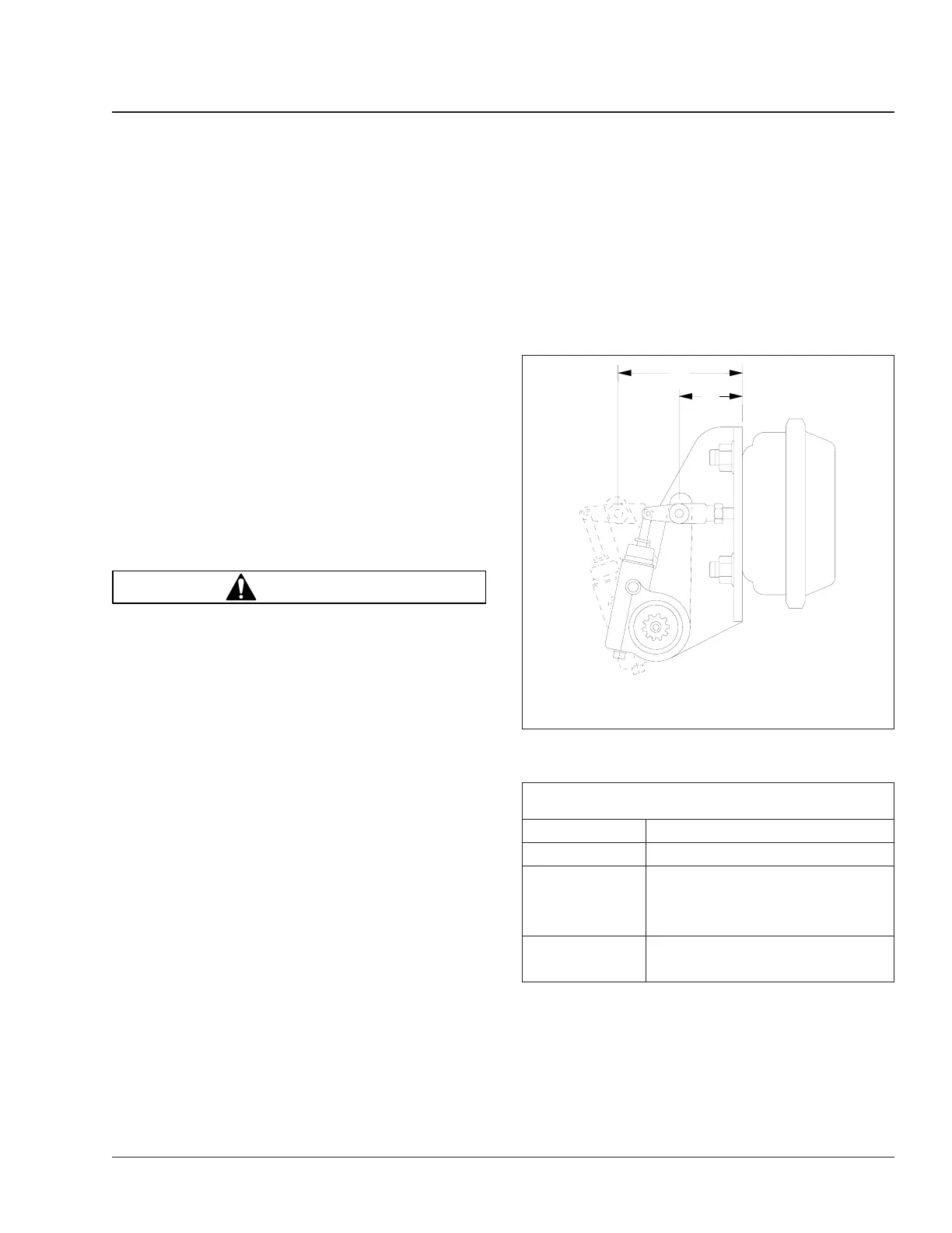
3.1 With the brakes fully released, use a ruler
to measure the distance from the bottom
of the brake chamber to the center of the
large clevis pin. See Fig. 11, Ref. A.
3.2 Build air pressure to at least 85 psi (585
kPa). Apply the brakes, then measure the
distance from the bottom of the brake
chamber to the center of the large clevis
pin. See Fig. 11, Ref. B. The difference
between the measurements is the brake
chamber stroke.
Compare this measurement with those
shown in Table 5.
4. If the brake chamber stroke exceeds the mea-
surements shown in Table 5, check the founda-
tion brakes for problems such as worn cams,
bushings, pins and rollers, or broken springs.
Repair or replace as needed. For instructions,
see Group 42 of the
Business Class
®
Trucks
Service Manual
.
5. If there are no problems with the foundation
brakes, manually adjust the slack adjuster as
follows:
5.1 Turn the adjusting hexnut three-quarters
of a turn counterclockwise. See Fig. 10.
Maximum Allowable Brake Chamber Stroke, with
Gunite Automatic Slack Adjusters
Chamber Size Maximum Allowable Stroke
12 Less than 1-3/8 inches (35 mm)
16
Less than 1-3/4 inches (44 mm)20
24
24 (long stroke)
Less than 2 inches (51 mm)
30
Table 5, Maximum Allowable Brake Chamber Stroke,
with Gunite Automatic Slack Adjusters
5.2 Keeping the wrench on the adjusting hex-
nut, have someone apply the brakes sev-
eral times while you watch the hexnut. It
f420434b
B
A
09/27/94
A. With the brakes released, measure this distance.
B. With the brakes applied, measure this distance.
Fig. 11, Brake Stroke Check, Gunite Automatic Slack
Adjuster
Brakes 42
Business Class Trucks Maintenance Manual, October 1998 42/13