QUANTUM
™
LX EVAPORATOR CONTROL PANEL
MAINTENANCE
090.610-M (MAY 2016)
Page 20
POWER SUPPLY (Q5)
DESCRIPTION
The power supply of the Q5 control panel consists a
single, 12 volt DC supply, and is located on the DIN rail
at the back of the enclosure.
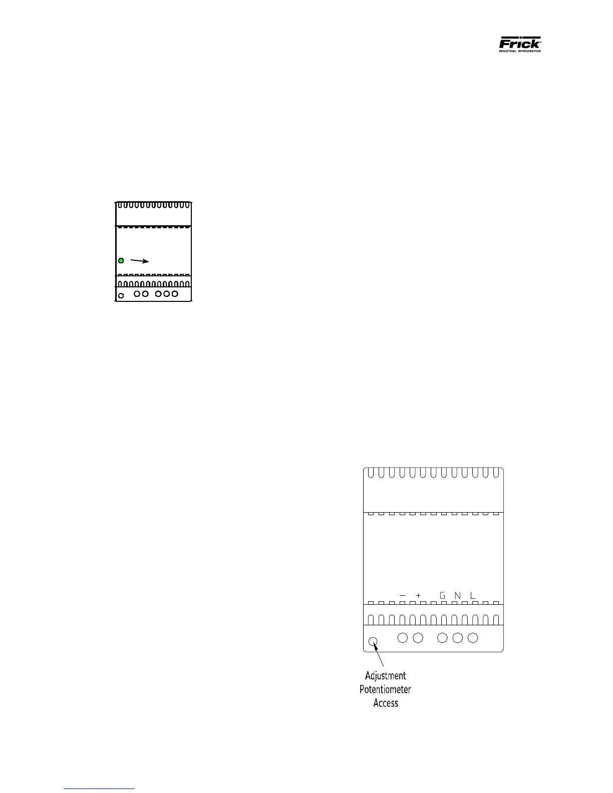
The supply is adjustable and has an indicator to show
that it is powered. Refer to the following page for the
location for the adjustment.
12 Volt DCPower Supply
POWER DISTRIBUTION
12 Volt DC Power is distributed to the Q5 processor
board and Interface Board.
MEASURING VOLTAGES
CAUTION! Measuring and adjusting the power supply
voltage requires the control power switch to be ener-
gized. Extreme care must be observed when taking any
readings, as 120 or 230 VAC (depending on incoming
system voltage) will be present next to the DC volt-
age connector. Adjusting the supply requires the use
of a small Philips screwdriver inserted into the supply
to access an adjusting potentiometer. CAUTION: It is
possible for the screwdriver (and the person mak-
ing the adjustment) to come into contact with po-
tentially lethal voltages. Proper Personal Protective
Equipment (PPE) measures need to be observed.
All circuit boards within the Q5 control panel require
accurately adjusted DC voltages in order to function
properly. Periodic measurement and adjustment of the
DC power system is recommended for optimum sys-
tem operation. Over time, it is possible for tempera-
ture, humidity, vibration and component age, to de-
grade the accuracy of these voltages. When any of the
DC voltages begin to stray from their optimum range,
mysterious problems can begin to arise.
Even with a perfectly adjusted supply, it is possible for
a potential drop in voltage at each connection point.
This drop normally is in the millivolt range, but un-
der some conditions, the drop can be much greater (as
high as tenths of a volt). Some examples of problems
could be:
• Loss of or intermittent communications fail-
ures.
• Q5 reboots for no apparent reason.
Power ON
Indicator
• LED’s on the Q5 are lit, but nothing appears on
the display.
To perform measurements and adjustments on the
power supply voltage, use a reliable, calibrated Digi-
tal Volt Meter (DVM). The DVM should be accurate
to 1/100 of a volt DC. With the control power switch
turned ON, wait until the Operating Screen appears.
This is because the graphics required to create this
screen will draw more current than when the screen is
showing the normal POST (DOS) style messages during
a boot up. If the screen never appears however (possi-
bly due to a voltage problem), you will need to proceed
regardless of what is or is not displayed.
In order to properly measure the DC power system, it
must be checked at the DC power supply.
ADJUSTMENT
Ensure that the meter is set to the proper range (DC,
0-50 V or equivalent), as well as observing proper wire
polarity. The power supply drawing shown on the fol-
lowing page applies to all three power supplies. The
adjustment access hole for each supply is located on
the lower left of the front of the supplies. If an adjust-
ment is required, use a thin, Philips screwdriver, insert
the tip into the access hole for the appropriate voltage
potentiometer (refer to the diagram on the following
page for adjustment location). NOTE: Extreme care
must be used when adjusting the potentiometer.
Adjustment should only be performed by qualied
personnel. The use of a non-conductive device is
recommended.
+ -
DC
G N L
120 VAC
or
240 VAC
 Loading...


