QUANTUM
™
LX EVAPORATOR CONTROL PANEL
MAINTENANCE
090.610-M (MAY 2016)
Page 31
• The Power-I/O communications harness has a
problem (a new harness may be needed).
• A problem may exist with one of the I/O
boards (Digital or Analog).
• If the power LED is not lighted, check the cable
for proper connectivity. Note: Each board
provides the necessary connections to feed
all signals to the following connectors. If the
auxiliary Analog or Digital Board is not present
then a jumper plug (see Recommended Spare
Parts List) must be installed to daisychain the
signals.
The most common symptom that is be exhibited by a
low +5 Vdc voltage to the Digital Boards is an alarm
message that reads Digital Board Reset Shutdown.
ACTIVE LED
The Digital Board(s) have an Active LED indicator on the
board that blinks when the board’s software is running.
If the Active LED is not blinking, check to ensure that
the EPROM is installed properly. The EPROM is located
in chip slot U8, next to the power connector.
DIGITAL INPUTS
A Digital Input is the portion of the hardware that allows
devices such as limit switches, relay contacts, and
level switches, to interface with the Quantum™. The
software program within the Quantum™ is constantly
looking at these Input channels, via communications,
and based upon whether a control voltage is present or
not, will provide the necessary control for an associated
Output channel.
The following pictorial shows a side view of the 120
VAC Input module. The color of an Input module is
yellow:
Never plug a 120 Volt Input module into a 240 Volt
system, and vice-versa. Never plug an Output module
into a position designated for an Input module.
You will notice that when a module is plugged into the
Digital board, there is a fuse located directly adjacent
to the module. This fuse is of the plugable variety,
and must be plugged into the IN position for an Input
module.
DIGITAL OUTPUTS
A Digital Output is the portion of the hardware that
the Quantum™ is to control (energize). These devices
include solenoids, relay coils, and heaters to be
energized, based upon the logic within the Quantum™
LX software program.
The following pictorial shows a side view of the 120
VAC Output module. The color of an Output module
is black:
Although this Output module is labeled as 280 VAC on
the top, and on the side, it can be used on both 120 and
240 volt applications.
Never plug an Input module into a position designated
for an Output module.
You will notice that when a module is plugged into the
Digital Board, there is a fuse located directly adjacent
to the module. This fuse is of the plugable variety, and
must be plugged into the OUT position for an Output
module.
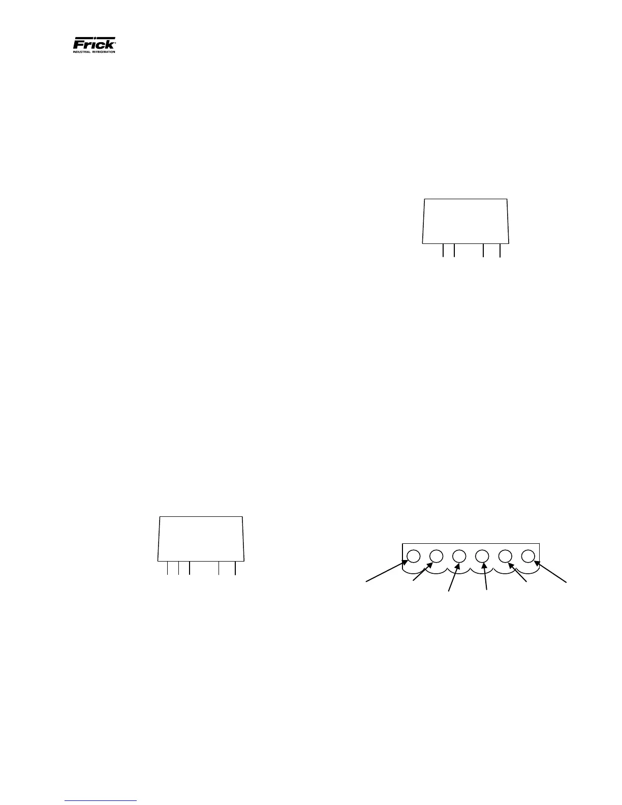
CHECKING THE DIGITAL INPUTS AND OUTPUTS
Some problems that may be encountered involve
troubleshooting the digital inputs and outputs. The
Digital I/O (Input / Output) Boards have six Digital I/O
(DIO) board connectors labeled P1 through P6. The Input
and Output modules are wired to a DIO connector plug.
Position 3 provides power and position 4 is a neutral on
the DIO connectors. Positions 1, 2, 5, and 6 are signal
connections, as shown below:
Signal
Signal
Signal
Signal
The Digital I/O board’s I/O modules are congured by
proper module selection, AC or DC, operating voltage,
input or output, and moving the fuse to the in or out
position. An LED is associated with each module and
displays the state of each module. A lit LED represents
an Input that is High, receiving a signal or an Output
that is On.
If a properly congured Digital I/O is not responding
correctly, rst look at the Digital Board on the Digital
I/O Screen and check if the module is on. If it is not on,
check if the LED on the Digital Board is also not lit. If
the LED is not lit, then check the fuse. If the fuse is OK,
then check the module.
 Loading...


