EasyManua.ls Logo

Frick QUANTUM LX Control Panel - Page 39

Frick QUANTUM LX Control Panel
64 pages
Print Icon
To Next Page IconTo Next Page
To Previous Page IconTo Previous Page
Loading...
QUANTUM
LX EVAPORATOR CONTROL PANEL
MAINTENANCE
090.610-M (MAY 2016)
Page 39
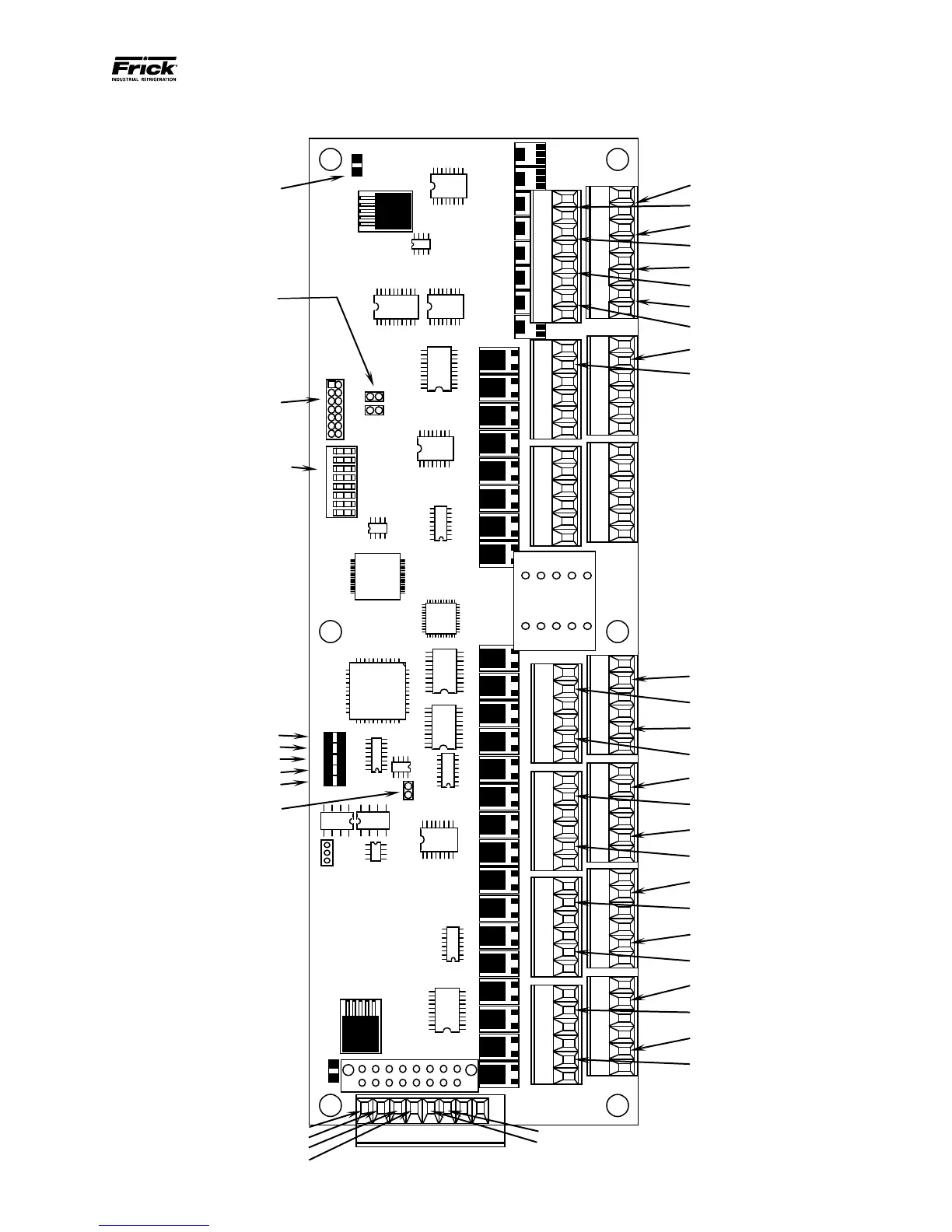
ANALOG BOARD PICTORIAL
P1 - J-TAGG Port
SW1 - DIP Switch
(See Settings Chart)
LK3 & LK4 -
Install for Vibration
Sensor Gain
(When needed)
D5 - +24Vdc Power LED
CH. 1 OutputVariable Speed (Zone A)
CH. 5 Output
CH. 2 OutputVariable Speed (Zone B)
CH. 6 Output
CH. 3 OutputVariable Speed (Zone C)
CH. 7 Output
CH. 4 Output
CH. 8 Output
CH. 5 Input Ammonia (Zone B)
CH. 7 Input
CH. 6 Input – Ammonia (Zone C)
CH. 8 Input
CH. 1 Input Control Temp. (Zone A)
CH. 3 Input Control Temp. (Zone C)
CH. 2 Input Control Temp. (Zone B)
CH. 4 Input Ammonia (Zone A)
CH. 9 Input
CH. 11 Input
CH. 10 Input
CH. 12 Input
CH. 13 Input
CH. 15 Input
CH. 14 Input
CH. 16 Input
+5 Vdc
+12 Vdc
+Tx/+Rx
-Tx/-Rx
D1 - +5Vdc Power
D9 - Active LED
D3 Not used
D2 Not used
D7 - COMM Rx LED
D8 - COMM Tx LE
D
LK1 - Install for 120 ohm terminator
on RS-485 Communications
Part #: 640D0168H01
Revision:
Serial #:
P1
LK3
LK4
1
2
3
4
5
6
7
8
SW1
Open
U4
U7
U8
U6
U1
LK1
U15
U3
U2
P4A (Inputs)
(CH1) (CH2)
P4B (Inputs)
(CH3) (CH4)
P5A (Inputs)
(CH5) (CH6)
P5B (Inputs)
(CH7) (CH8)
P6A (Inputs)
(CH9) (CH10)
P6B (Inputs)
(CH11) (CH12)
P7A (Inputs)
(CH13) (CH14)
P7B (Inputs)
(CH15) (CH16)
P9A (Inputs)
(CH17) (CH18)
P9B (Inputs)
(CH19) (CH20)
P10A (Inputs)
(CH21) (CH22)
P10B (Inputs)
(CH23) (CH24)
P11B (Outputs)
(CH5) (CH6) (CH7) (CH8)
P11A (Outputs)
(CH1) (CH2) (CH3) (CH4)
U10
U20
U19
U21
U11
U24
U22
U12
D5
24VDC
D1
5VDC
D9
Act
D3
CRx
D2
CTx
D7
Rx
D8
Tx
P2
P12
U15
U16
U14
U17
U18
U13
U23
CH. 17 Input
CH. 19 Input
CH. 18 Input
CH. 20 Input
CH. 21 Input
CH. 23 Input
CH. 22 Input
CH. 24 Input

Related product manuals