39 PB
WARNING
ELECTRIC SHOCK HAZARD
Turn off electric power before service or
installation. Extreme care must be used, if it
becomes necessary to work on equipment with
power applied.
Failure to do so could result in serious injury or
death.
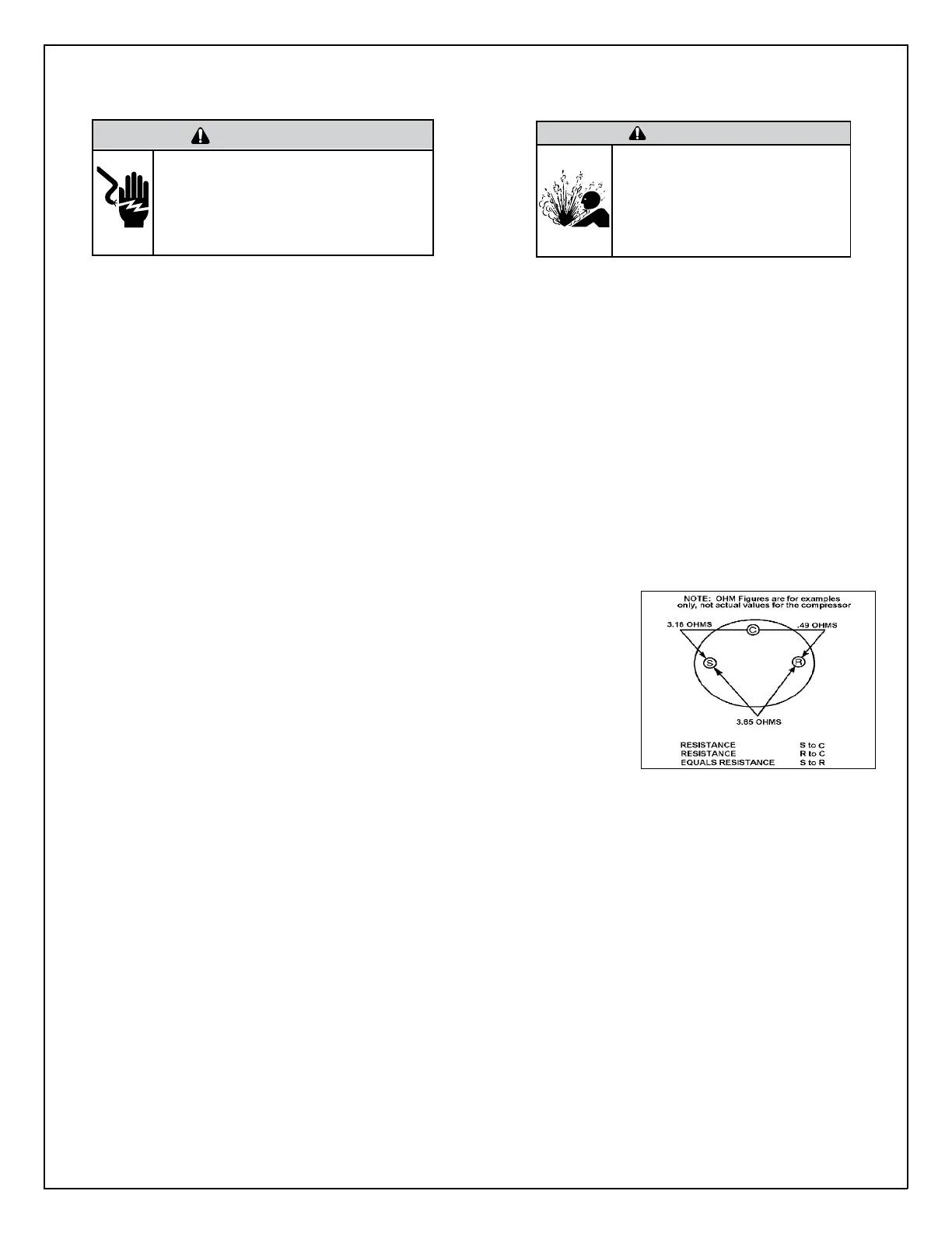
Single Phase Resistance Test
Remove the leads from the compressor terminals and set the ohmmeter on the lowest scale (R x 1).
Touch the leads of the ohmmeter from terminals common to start (“C” to “S”). Next, touch the leads of the ohmmeter from terminals
common to run (“C” to “R”).
Add values “C” to “S” and “C” to “R” together and check resistance from start to run terminals (“S” to “R”). Resistance “S” to “R” should
equal the total of “C” to “S” and “C” to “R.”
In a single phase PSC compressor motor, the highest value will be from the start to the run connections (“S” to “R”). The next highest
resistance is from the start to the common connections (“S” to “C”). The lowest resistance is from the run to common. (“C” to “R”) Before
replacing a compressor, check to be sure it is defective.
GROUND TEST
Use an ohmmeter set on its highest scale. Touch one lead to the compressor body (clean point of contact as a good connection is a must) and
the other probe in turn to each compressor terminal. If a reading is obtained the compressor is grounded and must be replaced.
Check the complete electrical system to the compressor and compressor internal electrical system, check to be certain that compressor is
not out on internal overload.
Complete evaluation of the system must be made whenever you suspect the compressor is defective. If the compressor has been operating for
sometime, a careful examination must be made to determine why the compressor failed.
Many compressor failures are caused by the following conditions:
1. Improper air ow over the evaporator.
2. Overcharged refrigerant system causing liquid to be returned to the compressor.
3. Restricted refrigerant system.
4. Lack of lubrication.
5. Liquid refrigerant returning to compressor causing oil to be washed out of bearings.
6. Non-condensables such as air and moisture in the system. Moisture is extremely
destructive to a refrigerant system.
7. Capacitor.
CHECKING COMPRESSOR EFFICIENCY
The reason for compressor inefciency is normally due to broken or damaged suction and/or
discharge valves, reducing the ability of the compressor to pump refrigerant gas.
NOTE: Before installing valves and gauges, check the compressor discharge temperature and
compressor current, Low compressor amperage combined with low discharge temperature is
an indication that the compressor might be faulty,
This condition can be checked as follows:
1. Install a piercing valve on the suction and discharge or liquid process tube.
2. Attach gauges to the high and low sides of the system.-
3. Start the system and run a “cooling or heating performance test.” If test shows:
A. Below normal high side pressure
B. Above normal low side pressure
C. Low temperature difference across coil
The compressor valves are faulty - replace the compressor.
WARNING
HIGH PRESSURE HAZARD
Sealed Refrigeration System contains refrigerant
and oil under high pressure.
Proper safety procedures must be followed,
and proper protective clothing must be worn
when working with refrigerants.
Failure to follow these procedures could
result in serious injury or death.
Figure 606 (Resistance Chart)
COMPONENT TESTING
Compressor Checks
 Loading...