EasyManua.ls Logo

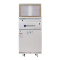
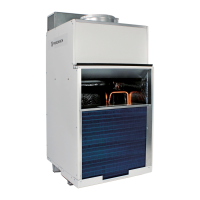
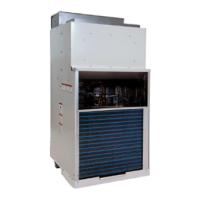
Friedrich VRP Series User Manual

Friedrich VRP Series
41 pages
To Next Page IconTo Next Page
Page #1 background imageLoading...
Page #1 background image
Installation & Operation Manual
VRP IOM 92301001_02
PRECISION
US
C
12000 Btu
24000 Btu
Innovative | Intelligent | Inverter
Variable Refrigerant
Packaged Heat Pump
For Commercial and Residen-
tial Applications
One or more of the following
patents may apply:
10408504
10436457
10488083
Additional patents pending

Other manuals for Friedrich VRP Series

Questions and Answers:

Friedrich VRP Series Specifications

General IconGeneral
BrandFriedrich
ModelVRP Series
CategoryHeat Pump
LanguageEnglish

Summary

General Safety Information

Electrical Shock Hazard

Details electrical shock hazards and necessary precautions during installation and servicing.

Refrigeration System Hazards

Highlights high-pressure refrigeration system risks like puncturing or exposing to heat.

Safety Alert Symbols and Meanings

Explains the safety alert symbol and the meaning of WARNING, CAUTION, and NOTICE.

Safety Device Integrity

Warns against disabling or bypassing unit safety devices, which can cause fire, injuries, or death.

General Specifications

Product Nomenclature

Explains the coding system used to identify VRP models and their features.

Cooling Performance Data

Provides detailed cooling performance metrics for VRP12K/VRP12R and VRP24K/VRP24R models.

Heat Pump Performance Data

Lists heat pump performance metrics, including rated and minimum/maximum BTU, HSPF, and power usage.

Unit Dimensions and Weights

VRP Dimensional Data 12K

Illustrates the physical dimensions and clearance requirements for the VRP 12K model.

VRP Dimensional Data 24K

Shows the physical dimensions and clearance requirements for the VRP 24K model.

Model Specification Summary

Tabulates dimensions, shipping weight, and R410A charge for different VRP models.

Electrical Specifications and Requirements

VRP Model Electrical Data

Details electrical parameters like voltage, heater watts, Btu, amps, MCA, and MOP/MOCP for VRP models.

Wire Size and Grounding

Specifies recommended wire sizes, fuse/circuit breaker types, and grounding requirements.

Electrical Rating Table

Lists recommended branch circuit breaker sizes and corresponding AWG wire sizes.

Air Flow and Static Pressure Data

Indoor CFM vs. External Static Pressure

Presents data and graphs for indoor fan airflow at various external static pressures for VRP models.

Condenser CFM vs. External Static Pressure

Details condenser fan airflow and external static pressure ratings for VRP units.

Installation Clearances

Building Exterior Opening Requirements

Specifies minimum distances for unit placement on exterior walls and between units.

Grill Clearance Requirements

Outlines minimum clearances from obstructions around the unit's exterior louvered grill.

Installation Orientations

Front Installation Orientation

Details the top view and required dimensions for front installation through a wall.

Left Installation Orientation

Shows the top view and required dimensions for left-side installation through a wall.

Right Installation Orientation

Illustrates the top view and required dimensions for right-side installation through a wall.

Exterior Wall Opening Dimensions

Compact vs. Standard Opening Sizes

Lists width and height for compact and standard exterior wall rough openings for VRP units.

Opening to Floor Clearance

Notes the required 3-inch distance between the rough opening and the finished floor/platform.

Interior Wall Opening Dimensions

Return Air Access Door Cut-Out

Specifies the dimensions for the interior wall cut-out for the return air access door.

Platform Height Consideration

Advises on total unit height relative to the interior rough opening for serviceability.

Preliminary Plumbing Requirements

Drainage System and P-Trap

Details the need for a drainage system with a P-trap to prevent waste gas entry into the living space.

Trimmed Wall for Installation Access

Explains wall trimming for access during installation, showing a detail view.

Wall Plenum Installation

Plenum Kit Components and Materials

Lists plenum kit parts and field-supplied materials like sealant and screws.

Step 1: Outside Plenum and Divider

Guides on preparing the opening, flashing, sealing the outside plenum, and installing the divider.

Step 2: Inside Plenum Assembly

Details applying sealant, placing the baffle, flashing the interior, and inserting the inside plenum half.

Step 3: Securing the Plenum Assembly

Instructs on drilling pilot holes and installing fasteners to secure both plenum halves.

Louver Installation

Louver Installation Before Plenum

Describes attaching the louver to the outside plenum half prior to wall plenum installation.

Louver Installation After Plenum

Explains the process of installing the louver from inside the closet after the wall plenum is in place.

Final Wall Plenum and Louver Sealing

Plenum Divider Extension Plate Installation

Details the installation of the plenum divider extension plate to the architectural louver.

Weather Strip and Sealing

Emphasizes ensuring the weather strip is intact and applying lubricants for proper sealing.

Unit Installation Preparation

Pre-installation Requirements

States that louver, plenum, plumbing, and wiring must be complete before final chassis installation.

Unit Placement Overview

Shows the unit positioned near the wall opening for front-install configuration.

Final Unit Placement and Connection

Covers powering off, moving the unit, inserting into plenum, connecting drain, ductwork, controller, and power.

Side Configuration Installation

Preparing for Side Installation

Shows the unit prepared for side installation adjacent to the closet.

Side Installation Process

Details sliding the unit into the closet and backward into the plenum for side-install applications.

Drain Installation

Connecting Drain Fittings

Guides on connecting supplied drain kit fittings to unit basepan and installing a field-supplied DWV system.

Drain Line Slope and Trapping

Specifies the 1/4" per foot slope for drain lines and the requirement for a trap.

Securing Unused Ports and Leak Check

Instructs on plugging unused ports and checking the system for leaks.

Ductwork Installation

Supply Air Duct Connection

Outlines installer responsibility for supply air duct connection per industry best practices.

Duct Transition and Length Guidelines

Advises on using sheet metal or duct board for transitions and maintaining minimum duct length.

Wall Controller Wiring

Wiring Color to Terminal Mapping

Shows the wire colors (Orange, Green/White, etc.) and their corresponding terminals (V+, D+, D-, V-, GND).

Cable Type Recommendation

Recommends using shielded and stranded CAT 6 cable with twisted pairs for wiring the wall controller.

Connecting Controller Wires to VRP Unit

Details stripping wires, inserting pairs into terminals, connecting ground shield, and securing connections.

Electrical Installation

Accessing the Power Terminal Block

Instructs on removing the electrical access panel to expose the incoming power terminal block.

Connecting Incoming Power Wires

Guides on inserting power wires (Ground, L1, L2) through the punched hole and fastening them.

Return Air Door Installation

Door Panel Mounting Options

Explains using hinge brackets for low (Option 1) or high (Option 2) return air openings.

Filter Installation and Usage Note

Details filter provision on the door and notes that unit and door filters should not be used together.

FreshAire™ System Setup and Operation

Initial FreshAire™ System Setup

Covers removing the blank-off plate before turning the unit on.

Engaging the FreshAire™ System

Explains how to activate the FreshAire™ System by flipping the switch to the ON position.

Electrical Wiring Diagrams

Diagram for 208/230V (7.5 & 10.0 kW)

Presents the wiring diagram for VRP models with 208/230V supply and 7.5 or 10.0 kW heating.

Diagram for 208/230V (2.5, 3.4, & 5.0 kW)

Shows the wiring diagram for VRP models with 208/230V supply and 2.5, 3.4, or 5.0 kW heating.

Diagram for 265V (2.5, 3.4, & 5.0 kW)

Illustrates the wiring diagram for VRP models with 265V supply and 2.5, 3.4, or 5.0 kW heating.

Diagram for 265V (7.5 & 10.0 kW)

Provides the wiring diagram for VRP models with 265V supply and 7.5 or 10.0 kW heating.

Basepan Heater Operation

Basepan Heat Thermostat Adjustment

Explains how to set the engagement temperature for the basepan heater using an analog thermostat.

Thermostat Settings and Hysteresis

Details the MIN/MAX settings and the 3F hysteresis for the basepan heat thermostat.

Final Installation Checklist

Chassis Operation Modes

Describes the operational conditions and set points for cooling, heat pump, and electric heat modes.

FreshAire™ System Operation

Explains the function and configuration options of the FreshAire™ System, including filter access.

Service and Warranty Information

Chassis Servicing and Removal

Details procedures for quick chassis change-outs and removal from the utility closet.

Routine Maintenance Procedures

Outlines regular maintenance tasks like cleaning coils, checking drains, and replacing air filters.

Warranty Information

Refers to authorized service providers and details warranty coverage and limitations.

Error Code Diagnostics and Test Mode

Explains how to enter and navigate the unit's error code menu for troubleshooting.

Available Accessories

Wall Plenum and Louver Options

Lists wall plenum kits and architectural louvers for different wall thicknesses and unit sizes.

Return Air Access Panel

Describes the optional return air access panel accessory.

Wall Controller Options

Details the standard Wall Controller and energy management versions with occupancy sensors.

Online Connection and Remote Access

Lists optional accessories for online connectivity and remote access to the system.

Diagnostic Error Codes

Error Code List and Descriptions

Provides a comprehensive list of diagnostic codes and their corresponding descriptions for troubleshooting.

Limited Warranty Information

Warranty Coverage and Limitations

Outlines the one-year parts and five-year sealed system warranty, excluding labor and specific damages.

Obtaining Warranty Service

Explains the procedure for obtaining warranty service by contacting authorized distributors or contractors.

Related product manuals