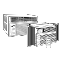
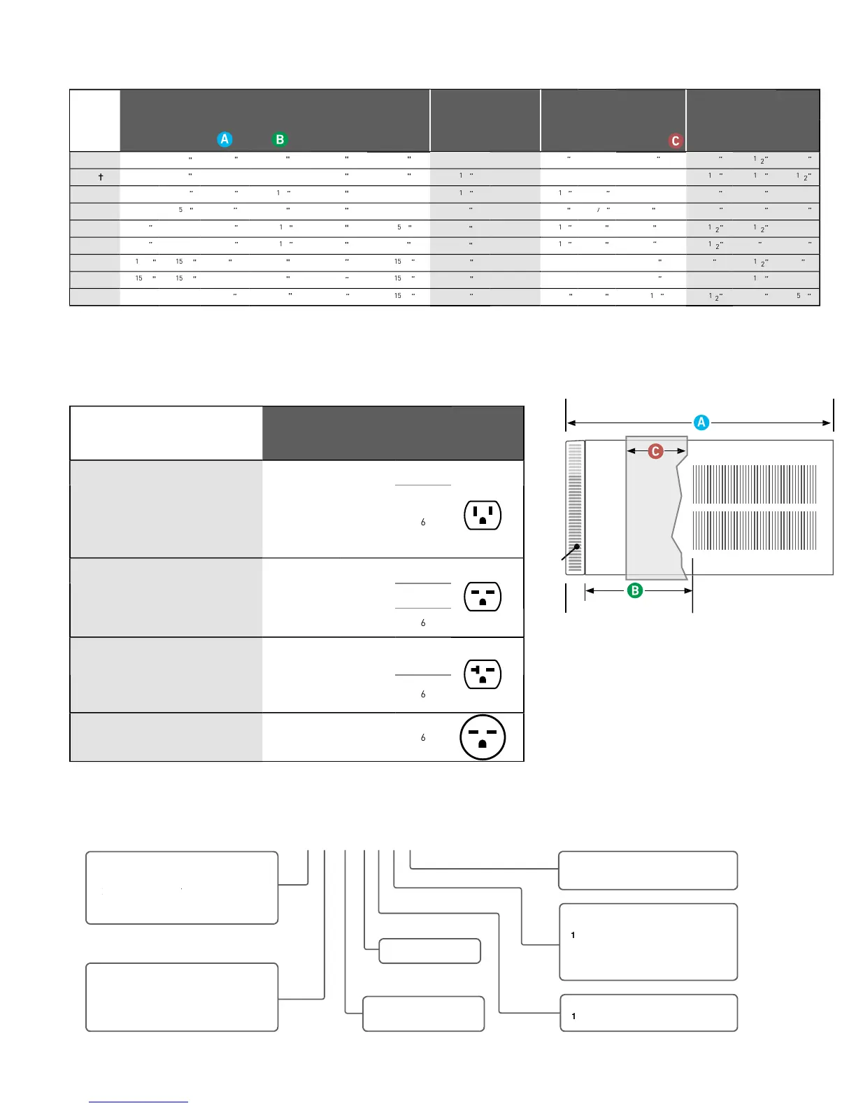
INSTALLATION INFORMATION/SLEEVE DIMENSIONS
inim
m
xt
n
i
n
wh
n m
nt
in
win
w.
Minimum widths achieved usin
one side curtain assembl
as opposed to both in a standard installation.
leeve P1 does not have In-wall hole dimensions, as these units are
xed chassis and should not be installed In-wall.
N
TE:
,M and L sleeves ma
be installed in window with no side kits i
properl
installed.
Room Air Conditioner Model Identification Guide
L 2
N
0
F
N
TI
Straight Cool
–Straight Cool
–
ctr
c
a
HA
I
–
orta
–
rogramma
Small
hassis
–Medium
hassis
–Large Chassis
M
DEL
ERIE
APPR
XIMATE
Btu (000) Cooling
V
LTA
E
–11
o
ts
–230/208 Volt
– Straight Cool and
115
eat
ump
o
e
– 1
eat str
p,
om
na
– 3
eat str
p,
om
na
– 4
eat str
p,
om
na
– 5
eat str
p,
om
na
L
tt
r at
nd of mod
l numb
r indicat
s
a modification to an existing model
B
C
r
n
IDE VIE
Sleeve Dimensions Drawing
Sleeve
Height
INCHES
Width
INCHES
Depth
with Front
INCHES
Shell Depth
to Louvers
INCHES
Minimum
Extension
Into Room*
INCHES
Minimum
Extension
Outside
*
INCHES
Window Width
INCHES
In-wall Installation
Finished Hole
INCHES
Carton Dimensions
INCHES
Minimum** Maximum Height Width Max. Depth
Height Width Depth
Q 14
9
21
2" 42
4
2
"
3
/4
5
22
1
2"
"
"
2
6
T F
R THR
-WALL
2
7
/
/
/
4
6
/
/
/
”
P7 15" 2
1
8
4
2
5
9"
5
8
8
26
2
/
2
2
42
7
8
9
21
29
29
P9
6
/
26
0
/
0
9
6
42
7
/8
6
21
/
8
7
5
6
5
6
2
8
6
27
42
6”
26
6”
34
2
M 17
6
6
29
6
27
42
16
2
6”
7
1
4
2
29
L
0
6"
28" 35
6
8
6
29
42
20
8
5
24
38
7
1
Circuit Rating
Breaker
Model
Circuit Rating
Breaker or
T-D Fuse
Plug Face
(NEMA#)
Power Cord
Length (ft.)
Wall Outlet
Appearance
P
1
P
6
1
P
1
P1
1
P1
1
and
P15
1
. EP
11. All
M
DEL
.
E
N11.
N1
A
1
N1
1
N1
and
14N1
A. Y
1
N1
A.
1
5V - 15
-
CP18G
5
V - 15A
- 15P
SS12N30
SS16N30
SM16N10
SM18N30 and SM21N30.
4 1
CP24G30.
EP12G
, EP18G
, EP24G
SM24N
0A. SL24N
0 and SL28N
0.
ES12N
and ES16N
. YS12N
.
2
0V - 20A
- 2
P
SL
6N
0. EM18N
4
EM24N
4A and
EL
6N
. YM18N
4 and YL24N
.
2
0V -
0A
-
0P
15
Commercial_Room_Air_Conditioners_Brochure_2013 (6-13).indd 15 6/6/2013 1:51:45 PM
 Loading...