Chapter 1
Page 14
1.9 Completing The Setup
Once the perimeter wire is completed and pegged to the ground, the last step to complete is
attaching the Perimeter Switch to the perimeter wires and testing the setup. Be sure the wire lead
coming out of the Perimeter Switch is positioned at the small notch in the bottom of the housing
before fully snapping the Perimeter Switch back together. Figure 1.14. The lead coming from out of
the Perimeter Switch has a female connector permanently attached. It is one part of a two-part
connector. Figure 1.15 and 1.16. Insert the two perimeter wire ends into the male connector as
shown in Figure 1.17. Using a small flat blade screwdriver, fasten the two screws tightly to hold the
wire. Figure 1.17. Plug the perimeter wire connector into the Perimeter Switch and press the on
button. A small flashing green light next to the ‘On’ button indicates the system is on and
functioning correctly. Figure 1.18. The Perimeter Switch also has an indicator for low batteries and
for a disconnected/broken perimeter wire. Figure 1.18. The Perimeter Switch has an automatic
shutoff feature, eliminating the need for you to turn it off after each use. It will shut itself off after 5
continuous hours of operation. Place the Perimeter Switch on the stake as shown in Figure 1.19 or
mount on a fixed surface as shown in Figure 1.20.
Figure 1.12
Figure 1.13
C-cell batteries,
place in battery
holder
Small notch for
wire lead
Two wire ends from
perimeter setup.
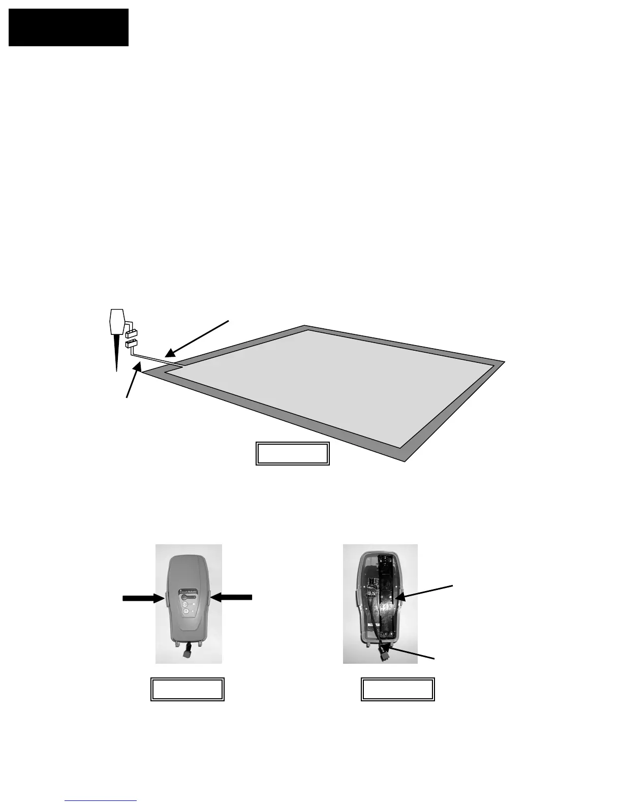
Switch > 5 feet (1.5 m)
from perimeter.
Note that the wires are adjacent and touching leading from the
perimeter to the Perimeter Switch. Peg firmly to the ground leading
away from the perimeter and towards the switch location
Squeeze at arrows to
remove cover
Figure 1.14
Chapter 1
Page 18