1.9CompletingTheSetup
Oncetheperimeterwireis completedandpeggedtotheground,the last step to complete is
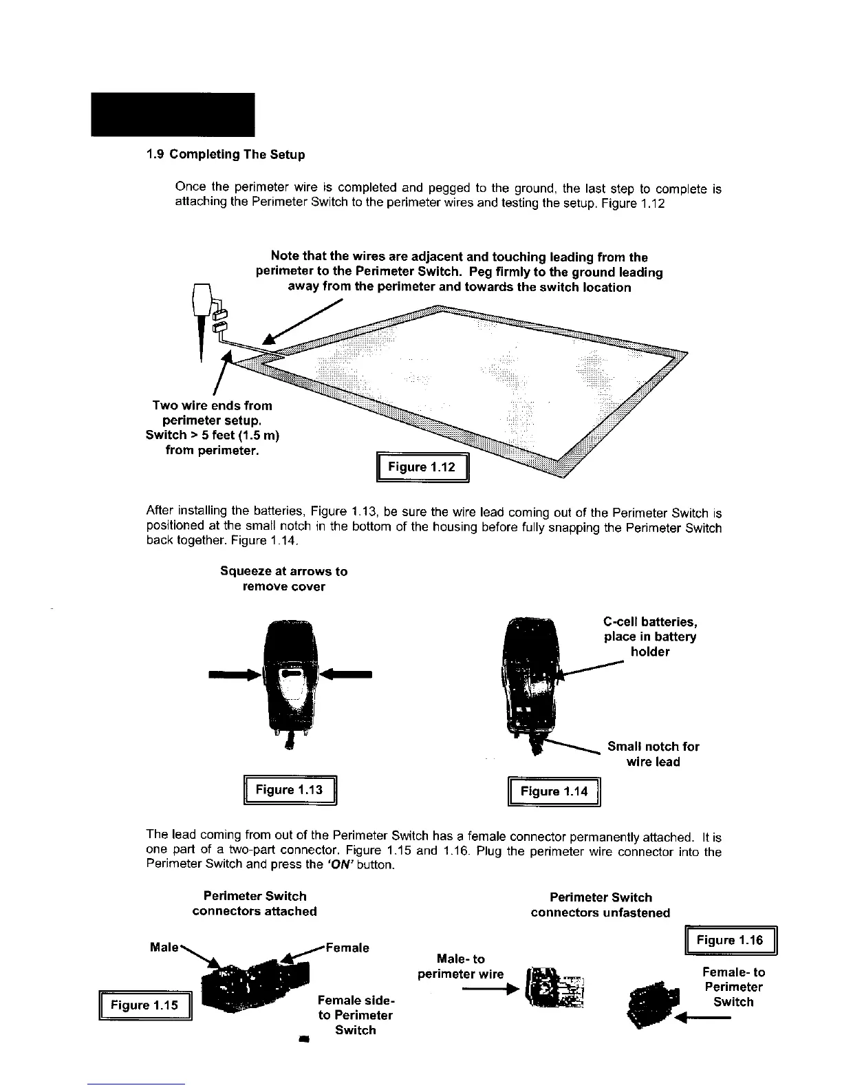
attaching the Perimeter Switch to the perimeter wires and testing the setup. Figure 1.12
Note that the wires are adjacent and touching leading from the
perimeter to the Perimeter Switch. Peg firmly to the ground leading
_4 away from the perimeter and towards the switch location
Two wire
perimet
Switch > 5
from pe
After installing the batteries, Figure 1.13, be sure the wire lead coming out of the Perimeter Switch is
positioned at the small notch in the bottom of the housing before fully snapping the Perimeter Switch
back together. Figure 1.14.
Squeeze at arrows to
remove cover
[iFigure,.13I [IF,gure,.1,I
C-cell batteries,
place in battery
holder
Small notch for
wire lead
The lead coming from out of the Perimeter Switch has a female connector permanently attached. It is
one part of a two-part connector. Figure 1.15 and 1.16. Plug the perimeter wire connector into the
Perimeter Switch and press the 'ON" button.
Perimeter Switch
connectors attached
I Figure 1.15 i Female side-
to Perimeter
Switch
all
Male- to
perimeter wire
Perimeter Switch
connectors unfastened
I Figure1-16 I
Female- to
_pl<l. Perimeter
Switch