the hood duct and release the snap band from
the hood duct.Remove one (1) screw holding the
Hood fan motor on the rear cavity
5. Remove the hood fan motor from the oven cavity top
plate by lifting it up.
6. Now, the hood fan motor is free.
1. Disconnect the power supply cord , remove the oven
from wall and remove outer case (Refer to procedure
of "Removal of Oven from Wall" and "Outer case
Removal".)
2. Open the door and block it open.
3. To discharge the high voltage capacitor, wait for 60
seconds.
4. Disconnect the high voltage wire lead of the high voltage
rectifier assembly from the magnetron.
5.
Disconnect the filament lead of the transformer from the
magnetron.
6. Disconnect the wire leads of magnetron TCO.
MAGNETRON REMOVAL
7. Carefully remove three (3) mounting screws holding the
magnetron to waveguide. When removing the screws
hold the magnetron to prevent it from falling.
8. Remove the magnetron from the unit with care so the
magnetron tube should not be hit by any metal object
around the tube.
CAUTION: WHEN REPLACING THE MAGNETRON, BE
SURE THE R.F. GASKET IS IN PLACE AND
MOUNTING SCREWS ARE TIGHTENED SE-
CURELY.
1. Disconnect the power supply cord , remove the oven
from wall and remove outer case (Refer to procedure
of "Removal of Oven from Wall" and "Outer case
Removal".)
2. Open the door and block it open.
3. To discharge the high voltage capacitor, wait for 60
seconds.
4. Disconnect the high voltage wire lead with high voltage
rectifier from the magnetron.
5.
Disconnect filament lead of the transformer from high
voltage capacitor.
6. Disconnect high voltage wire from capacitor.
HIGH VOLTAGE RECTIFIER AND HIGH VOLTAGE CAPACITOR REMOVAL
7. Remove one (1) screw holding capacitor holder and
high voltage rectifier to the fan duct.
8. Disconnect the high voltage rectifier assembly from the
high voltage capacitor.
9. Now, the high voltage rectifier assembly is free.
Remove capacitor from the holder.
10.Now, the high voltage capacitor is free.
CAUTION: WHEN REPLACING THE HIGH VOLTAGE
RECTIFIER ASSEMBLY, THE GROUND SIDE
TERMINAL MUST BE SECURED FIRMLY WITH
A GROUNDING SCREW.
THERMAL CUT-OUT (CAVITY) REMOVAL
1. Disconnect the power supply cord.and remove the oven
from wall and remove outer case. (Refer to procedure
of "Removal of Oven from Wall" and "Outer case
Removal")
2. Open the door and block it open.
3. To discharge the high voltage capacitor, wait for 60
1. Disconnect the power supply cord and remove the hood
exhaust louver from the cavity. (Refer to procedure of
"Removal of Hood exhaust louverl"
2. Open the door and block it open.
3. Remove the one (1) screw holding the control panel to
the oven cavity front plate.
4. Up push the control panel and remove it from cavity and
HOOD FAN THERMAL CUT-OUT REMOVAL
hold it at the from plate by the control panel flange.
Disconnect the wire leads from the control panel.
4. Disconnect the wire leads from the hood fan thermal
cut-out.
5. Remove one (
1) screw holding the thermal cut-out to the
bottom plate (outer case side).
6. Remove the hood fan thermal cut-out from the bottom
plate.
7. Now, the hood fan thermal cut-out is free.
seconds.
4. Disconnect the wire leads from the thermal cut-out
(cavity).
5. Remove the thermal cut-out (cavity) from the holder at
the air duct.
6. Now, the thermal cut-out (cavity) is free.
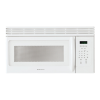
FMV157GQ
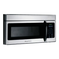
FMV157GC