Do you have a question about the Frigidaire FMV157GS and is the answer not in the manual?
Procedures to follow before servicing the microwave oven.
Safety checks and procedures before starting service on the oven.
Final checks and procedures after completing repairs on the oven.
Specifies limits and safety interlock requirements for microwave emission.
Outlines steps for preparing the oven and materials for leakage testing.
Details the procedure for conducting a closed-door leakage test.
General warnings about operating the oven and servicing it.
Identifies high-voltage components posing an electrical shock hazard during servicing.
Details the importance and procedure for proper grounding of the oven.
Specifies the electrical requirements and grounding for the oven.
Explains the sequence of component functions during oven operation.
Details the power level settings and their corresponding ON/OFF times for variable cooking.
Describes how hot air is discharged vertically from the oven.
Explains the horizontal discharge of hot air from the oven.
Details the method of recirculating air within the kitchen.
Illustrates the oven's schematic diagram when in the off condition.
Shows the oven's schematic diagram during cooking operation.
Explains door operation, sensing switches, and interlock systems.
Details the function of thermal cut-outs, turntable, cooling, and hood fan motors.
Describes the hood lamp and its controls.
Important notes and safety precautions for troubleshooting the microwave oven.
Steps to test the magnetron assembly for proper function.
Procedure to measure microwave output power using a water temperature rise test.
Instructions for testing the power transformer's continuity and resistance.
Details the procedure for testing the high voltage rectifier.
Steps to test the high voltage capacitor for shorts or open circuits.
Procedure for testing the oven cavity thermal cut-out.
How to test the magnetron temperature fuse for continuity.
Procedure to test the primary interlock switch operation.
Steps to test the door sensing switch for proper function.
How to test the secondary interlock relay (RY2) contacts.
Procedure for testing the monitor switch operation.
Steps to test the hood thermal cut-out.
Procedure for testing the hood fan motor and its associated circuit.
Outlines testing procedures for the touch control panel and its units.
Procedure to test the key unit of the control panel assembly.
Steps for testing various relays (RY1, RY2, RY4, RY5) within the oven.
Procedure to test the defrost function and its settings.
How to check the foil pattern on the printed wiring board as a fuse.
Procedure to test the noise filter unit for proper continuity.
Overview of the touch control panel's units and functions.
Details the functions and I/O signals of the Large Scale Integration (LSI) chip.
Provides detailed information on the input/output signals of the LSI.
Maps LSI pin numbers to their signals, I/O, and descriptions for the LCD display.
Safety guidelines for handling sensitive electronic components like CMOS LSI.
Procedures and precautions for servicing the touch control panel assembly.
Lists required tools and additional precautions for servicing the appliance.
Critical warnings regarding high voltage and microwave energy exposure before servicing.
Lists components that can be replaced without removing the oven from the wall.
Procedure for removing the hood exhaust louver from the oven.
Steps for removing the oven from the wall and its outer case.
Procedures for removing the power transformer and hood fan motor.
Procedures for removing the magnetron, rectifier, and capacitor.
Steps for removing hood fan and cavity thermal cut-outs.
Instructions for installing the cooling fan motor and ensuring proper rotation.
Procedures for removing turntable motor and hood lamp sockets.
Steps for removing oven lamp, socket, and control panel assembly.
Steps for removing door sensing, primary interlock, and monitor switches.
Procedures for adjusting door sensing, primary interlock, and monitor switches.
Steps for removing and reinstalling the oven door assembly.
Checks to perform after servicing the oven door for proper operation and safety.
Procedures for disassembling the door's choke cover and frame.
Steps for removing latch springs, heads, and the door panel.
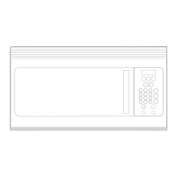
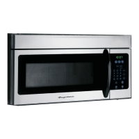
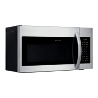
| Type | Over-the-Range Microwave |
|---|---|
| Capacity | 1.5 cu. ft. |
| Power | 1000 Watts |
| Control Type | Electronic Touch |
| Color | Stainless Steel |
| Cooking Presets | Yes |
| Turntable Diameter | 12 inches |
| Sensor Cooking | Yes |
| Child Lock | Yes |
| Defrost Function | Yes |
| Keep Warm Function | Yes |