Page 3
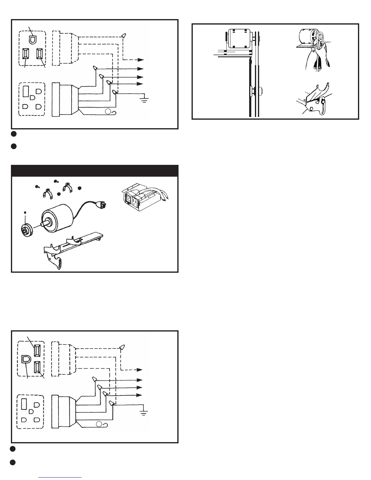
The orange wire is not used. Double it over and cover the bare end with
electrical tape.
A
INSTALLATION
1. Install the motor in the mounting cradle as shown.
2. Remove the junction box from the cooler.
3. Remove 120 volt pump and pump receptacle furnished with cooler and
replace it with the 240 volt LSP-94 pump and pump receptacle. (see
replacement parts list)
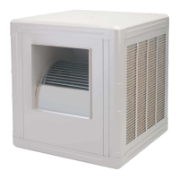
4. Wire the pump and motor receptacles per the schematic shown above.
5. Place both receptacles in the junction box as shown and re-attach the
junction box to the cooler top.
240 VOLT MOTOR KIT
The white wire is not used. Double it over and cover the bare end with
electrical tape or wirenut.
A
A
B
Green
Black
White
15A 120V
5 Pin
Motor
Recp.
Red
Black
White
Green
Orange
GND
Green
White
Black
Red
Pump
Black
Green
White
Lo
Hi
Com
Power
Supply
3 Pin
Green
Black White
15A 120V
Black
Green
White
3 Pin
Pump
Black
Red
White
Green
Lo
Hi
ComRed
Black
White
Green
Orange
5 Pin
A
Motor
Recp.
GND
A
Green
Black
Orange
15A 230V
5 Pin
Motor
Recp.
Red
Black
Orange
Green
White
GND
Green
Orange
Black
Red
Pump
Black
Green
Orange
Lo
Hi
Com
Power
Supply
3 Pin
B
Green
Black Orange
15A 230V
Black
Green
Orange
3 Pin
Pump
Black
Red
Orange
Green
Lo
Hi
Com
Red
Black
Orange
Green
White
5 Pin
A
Motor
Recp.
GND
Power
Supply
Power
Supply
120 VOLT MOTOR KIT
BLOWER BELT ADJUSTMENT
Correct belt tension adjustment is important. Incorrect adjustment increases
power consumption and shortens belt and motor life.
Install belt over motor and blower pulleys.
(A) check belt tension by squeezing (deecting) belt. Proper tension will allow
deection of 1/2 to 3/4 inch.
(B) To increase or decrease belt tension, loosen bolt in slot of motor support
brcket. Adjust belt to desired tension and re-tighten bolt.
OPERATION
PRE-WET PADS
For maximum cooling efciency, prior to the initial start up of the cooler
remove the pad frame assemblies from the cooler and spray the pad and
frames thoroughly with water from a garden hose.
Put the pad frame assemblies back on the cooler and while the pads are still
wet start the cooler with the pump on.
BUILT-IN WINTER CLOSURE (Down discharge units only)
An exclusive feature of your cooler (models in the 4800 to 6800 CFM range)
which is provided is the full closure damper. Your cooler is shipped from the
factory with the damper temporarily fastened to the side of the blower with a
shipping screw. Remove the screw and store the damper for later use during
winter months.
1. For Winter use of a damper, slide damper into cooler below the blower.age.
2. When starting the cooler in the Spring, remove the damper and store in a
safe place.
B
The red wire is not used on single speed motors. Double it over and cover
the bare end with electrical tape.
B
The red wire is not used on single speed motors. Double it over and cover
the bare end with electrical tape or wirenut.
 Loading...