Installation:
1. Locate a structural steel beam ange capable of withstanding a 5,000-lbf. static load or
meeting OSHA 1926.502 requirements for a safety factor of two.
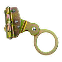
2. Push in on the latch handle to allow the adjustable hook to move.
3. Keeping the unit perpendicular to the beam, t the hooks over the edges of the beam ange.
4. Slide the adjustable hook so that both hooks are snug against the beam ange.
5. Pull back the adjustable hook to ensure the ratchet teeth are fully seated in the nearest
ratchet notches.
6. Tug, rock, and twist the anchor in all directions to ensure that it cannot come o of the ange.
*Always re-adjust according to Installation steps 1-6 when moving to a new or dierent
sized beam.
**D-ring is centered on the anchorage connector for ease of sliding on beam anges.
Particularly in rope access applications, bodyweight may disengage the centering feature
in some loading conditions. This is not a safety concern, but it may aect usability.
(Adjustable Directions)
(Notches)
(Latch Handle)
(Notches)
(Latch Handle)
(Adjustable Hook) (Adjustable Hook)
PERFORMANCE:
Static Tensile Strength: 5000-lbf (22kN)
Maximum Capacity: One worker with max
weight of 310-lbs when used as a single
point anchorage connector for personal fall
arrest or restraint system
DIMENSIONS:
Weight: 3.5-lbs
Beam Flange Width Range: 3.5”-14”
Beam Flange Thickness: .25“ to 1.25”
REGULATORY COMPLIANCE:
ANSI Z359.18 Type A, ANSI Z359.7-2011,
OSHA 1926.502, OSHA 1910.66,
COMPONENT MATERIALS:
Aluminum: Cross Bar
Bronze: Clamps
Stainless Steel: D-Ring Bracket
Zinc Plated Steel: D-Ring, Spring, Hardware
MFG:YYYYMMDD