Do you have a question about the FrSky R9M and is the answer not in the manual?
Details on RF power, operating voltage/current, channels, and compatibility.
Explanation of LED status lights for binding and normal operation.
Information on the external power input specifications.
Steps for binding the R9M 2019 module with receivers in R9M mode.
Steps for binding the R9M 2019 module with receivers in PPM mode.
Guide to setting telemetry modes on Taranis series transmitters.
Guide to setting telemetry modes on Horus series transmitters.
Configuration for 25mW telemetry modes with different channel outputs.
Configuration for 200mW and 500mW non-telemetry modes.
Steps to enable/disable S.Port on Taranis transmitters.
Steps to enable/disable S.Port on Horus transmitters.
Explanation of No Pulse, Hold, and Custom failsafe modes.
Detailed steps for setting custom failsafe positions for each channel.
The FrSky R9M 2019 (EU) telemetry module is a sophisticated long-range RC system operating at 868MHz, designed to provide reliable and precise control for various flight situations. This module offers two distinct operational modes, allowing users to adapt its performance to different flying conditions. It is a key component for enthusiasts seeking extended range, low latency, and high precision in their remote-controlled applications.
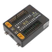
The R9M 2019 module serves as an external RF module for compatible FrSky transmitters, facilitating communication with R9 series receivers. Its primary function is to transmit control commands from the transmitter to the receiver and, in telemetry-enabled modes, to receive data back from the receiver to the transmitter. This bidirectional communication is crucial for monitoring various aspects of the model's performance, such as battery voltage, signal strength, and other sensor data.
The module features a Smart Port for telemetry data transmission, allowing for a full-duplex digital transmission interface. This means that multiple Smart Port-enabled devices, including receivers, sensors, and dashboards, can be connected without limitations on numbers or sequences, operating at a high transmission speed. This capability enhances the user's ability to gather comprehensive real-time information about their model.
The R9M 2019 module supports both PXX and CPPM modulations, with automatic detection, ensuring compatibility with a wide range of FrSky transmitters. It operates on an RF operating frequency of 868MHz, which is optimized for long-range applications within the EU region.
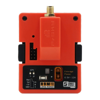
LED indicators on the module provide visual feedback on its operational status. A Green LED and a Red LED work in conjunction to indicate various states:
The module can be powered either externally or through the transmitter's module bay. If both external power and transmitter power are connected, the module automatically prioritizes the power source with the higher voltage, ensuring continuous operation.
The R9M 2019 module offers several usage features designed to enhance the user experience and adaptability:
Binding Procedure: The binding process uniquely associates a receiver with the transmitter RF module. The R9M module can be bound to multiple receivers, though only one can be used at a time. Conversely, a receiver can only be bound to one RF module.
Telemetry and No Telemetry Modes: The module supports both telemetry (25mW) and no telemetry (500mW/200mW) modes, allowing users to choose between data feedback and maximum power output.
S.Port Enable/Disable: The Smart Port functionality can be enabled or disabled.
Range Check Mode: A pre-flight range check is highly recommended before each flying session to ensure signal integrity. In this mode, the RF power is significantly reduced (to 1/30-1/10 of normal model range).
Failsafe Mode: The module supports three failsafe modes configurable on the transmitter:
The R9M 2019 module is designed for reliability, but ongoing maintenance practices are important for optimal performance and longevity:
Firmware Updates: FrSky continuously adds features and improvements to its products through firmware updates. Users are encouraged to regularly check the download section of the FrSky website (www.frsky-rc.com) for the latest firmware and manuals. Keeping the firmware updated ensures access to the newest functionalities, bug fixes, and performance enhancements.
Rebinding After Mode Switches: After switching between Telemetry (25mW) and No Telemetry (200mW/500mW) modes, the receiver must be rebound. This ensures that the module and receiver are correctly synchronized with the new operational parameters.
Environmental Considerations: The manual advises that reflections from nearby metal fences, concrete buildings, or trees can cause signal loss during both range checks and actual flights. Users should be mindful of their flying environment to minimize potential interference and maintain a clear line of sight.
Physical Inspection: While not explicitly detailed as a maintenance feature, regular physical inspection of the module and its connections (Smart Port, RS232 Serial Port, External Power Supply Port) can help identify any wear, damage, or loose connections that might affect performance.
By adhering to these usage and maintenance guidelines, users can ensure the FrSky R9M 2019 (EU) telemetry module provides a consistent, reliable, and high-performance long-range RC experience.
| Frequency Range | 868MHz / 915MHz |
|---|---|
| Modulation | LoRa |
| Telemetry | Yes |
| Firmware Upgrade | Yes |
| External Power Supply | Yes |
| Compatibility | FrSky receivers |