EasyManua.ls Logo

FrSky V8R7 User Manual

FrSky V8R7
9 pages
To Next Page IconTo Next Page
Page #1 background imageLoading...
Page #1 background image
Manual of Two-Way Radio System www.FrSky-rc.com P1of9
2.4GHz Two-Way Radio System
1. Introduction
The Two-way Radio System developed by FrSky provides an additional return link
that would be used for monitoring the Rx’s voltage, temperature, location, speed and so
on.
2. Overview
2.1 Transmitter modules:
a) Model: DFT
Compatible with the following transmitters:
Futaba: 3PM, 3PK, 7U, 8U, 8J, 9C, 9Z, 10C, FN series, T10C, FC-18, FC-28.
Hitec: Optic 6, Eclipse 7, Prism 7.
WFLY: WFT09, WFT08.
b) Model: DJT
Compatible with the following transmitters:
JR: 347/388/783/U8/PCM10/PCM10S/PCM10SX/PCM10IIS/8103/J9303/PX/9XII.
2.2 Receiver module:
a) Model: D8R, D8RHV
Compatible with FrSky Two Way module DFT/DJT.
b) Model: V8R, V8RHV, V8R7, V8R7HV, V8R4
V8 receivers work with DFT/DJT, just in receive-only mode.
3. Features
a) Advanced Continuous Channel Shifting Technology (ACCST SYSTEM)
achieves high reliable link in interference rich environments.
b) Easy to bind and instant link-up.
c) Excellent reboot times.
d) All channels failsafe.
Question and Answer IconNeed help?

Do you have a question about the FrSky V8R7 and is the answer not in the manual?

FrSky V8R7 Specifications

General IconGeneral
Type7-channel receiver
Frequency2.4 GHz
Channels7
Current Consumption30 mA
RangeUp to 1.5 km

Summary

Introduction to Two-Way Radio System

System Overview and Compatibility

Transmitter Modules

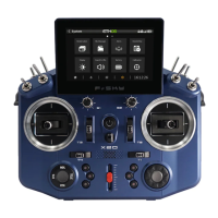
Lists compatible transmitters for DFT and DJT modules.

Receiver Modules

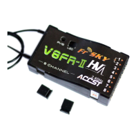
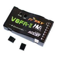
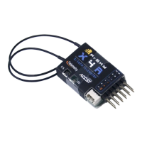
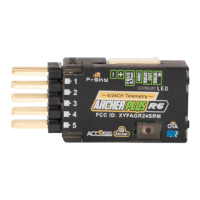
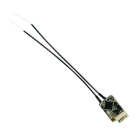
Lists compatible receivers for DFT/DJT modules.

Key Features of the System

Two-Way Communication Functionality

Technical Specifications

Receiver Specifications

Details specifications for the D8R receiver model.

Transmitter Module Specifications

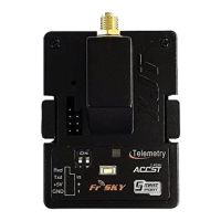
Details specifications for DFT and DJT transmitter modules.

System Usage and Setup

Setup and Installation

Instructions for system setup, transmitter module installation, and receiver/transmitter binding.

Range Check and Safety Indicator

Failsafe Functionality

Alarm and Pin Definitions

Alarm States and Sources

Describes audible alarm states and their sources.

Pin Definitions

Defines pins for receiver and transmitter modules.

LED Status Indicators

Transmitter Module LED Status

Explains LED indicators for the transmitter module.

Receiver LED Status

Explains LED indicators for the receiver.

Firmware Upgrade Process

Related product manuals