3
INSTALLATION
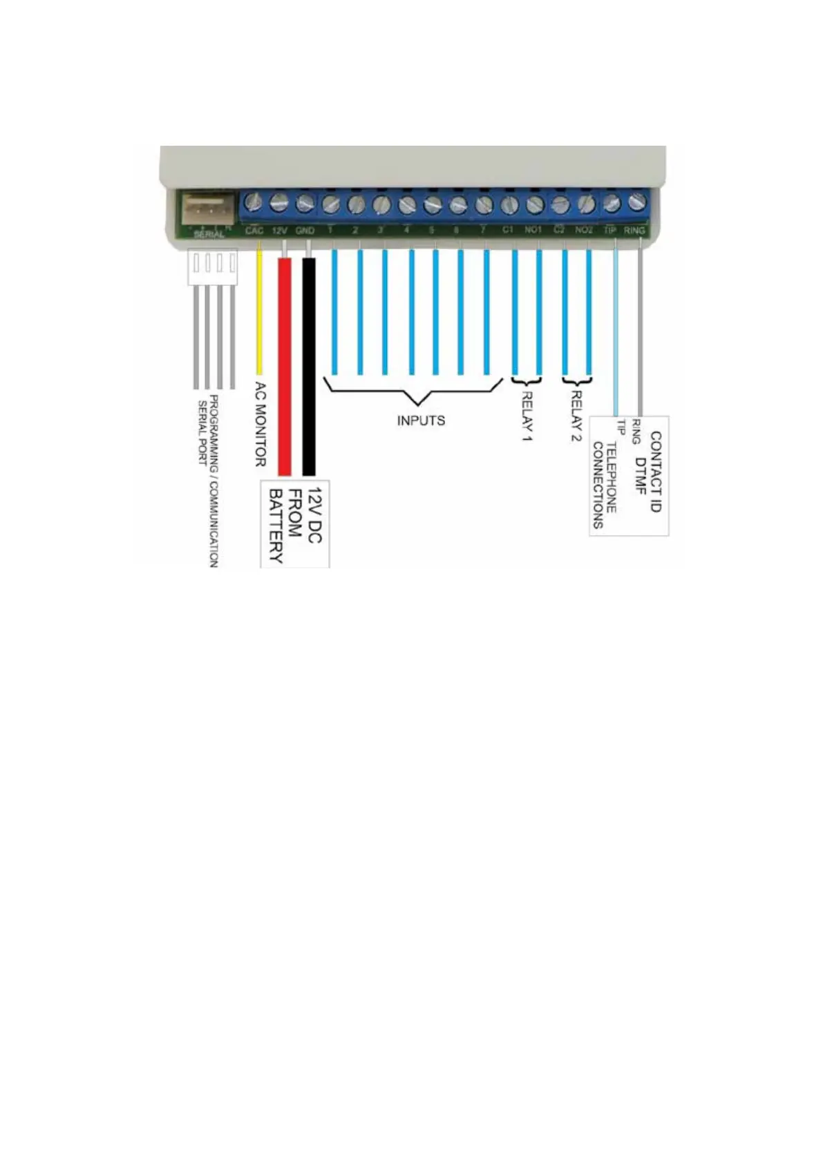
Connections to the TXC+ are shown below
Power Supply
The TXC+ must be connected to a stable 12V DC (nominal 13.2V) power supply. If a battery is
available in the alarm panel, it must preferably be powered directly from the battery
Check AC
• The Check AC (CAC) input detects the presence of the AC supply and is used to check for power
failure.
• The CAC line should be connected to one of the transformer’s SECONDARY terminals. Do NOT
connect this line to the mains.
• The CAC line will detect AC voltages between 10 and 24V.
• If the CAC line is not connected, the TXC+ should not be programmed to send AC Failure or
Restoral Signals.
Dry Contact Inputs
• The dry contact inputs can be used to detect alarms generated from the outputs of the Alarm
Panel or from other sources.
• If the external device generates the alarm by pulling the input to ground (negative trigger), the pull-
up jumper should be inserted on the input of the TXC+.
Contact ID Inputs
• The TXC+ can ‘intercept’ signals sent by the alarm panel on its telephone line (Contact ID)
interface. If the Contact ID interface is to be used, the Alarm Panel’s TIP and RING lines should be
connected to the TIP and RING lines on the TXC+.
• The alarm panel must be programmed to use its dialler, and the option for reporting must be set
to Contact ID. Refer to the programming manual of the applicable Alarm Panel.
• The TXC+ can be programmed to use its own account code or the account code of the alarm
panel when sending alarms received via the Contact ID interface.