Page 9 of 26 Rev. A
4 Battery Charger
The flow chart of charger is described as follows: (Figure S-3-A & Figure S-3-B)
4.1 When UPS is connected to the utility, the control power (+5Vdc) will be established
and the CPU will start to work.
4.2 When CPU turns on Main Relay (RY01), the AC power flows into Main Transformer.
4.3 Charging current will be generated from the inverter coil of the Main Transformer.
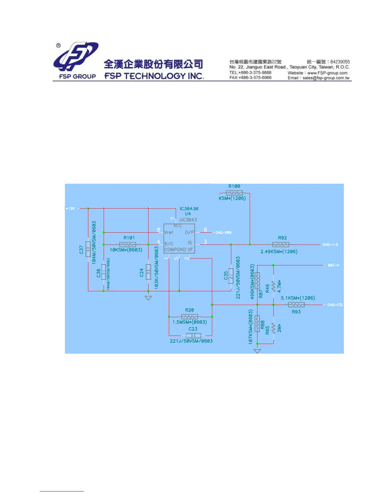
4.4 A PWM IC 3843 is used to adjust the charging voltage and charging current. (Refer
to Figure S-3-A) The charging voltage can be set by changing the value of R87, R88,
R46 and R65. The charging current can be set by changing the value of R14.
Figure S-3-A Charger Control Circuit
 Loading...