Page 21 of 26 Rev. A
11
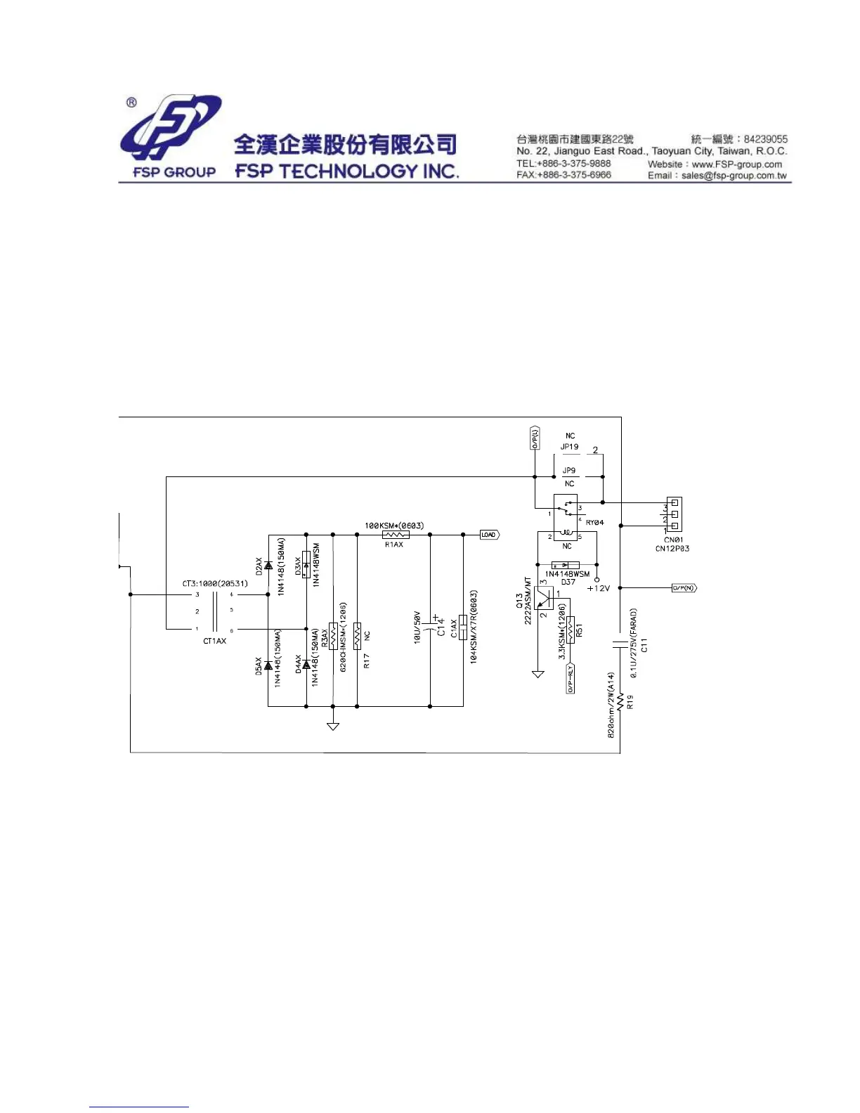
Load Detection Circuit
Load detection circuit is shown on Figure S-9. The output current is detected by current
transformer CT1AX. It lowers 1000 times of output current for CPU detection. The current
signal generated from CT1AX flows through a full-bridge rectifier and R3AX to convert to
a voltage signal (0~5 Volts). Then CPU can receive output current value of the UPS.
11.1 At line/boost/buck mode: The current value multiplies output voltage to get output
VA value.
11.2 At battery mode: Because the power factor of step wave is approximately equal to 1,
the current value multiplies 120V (230V) output voltage to get output Watt value.
Figure S-9 Load Detection Circuit