Page 6 of 26 Rev. A
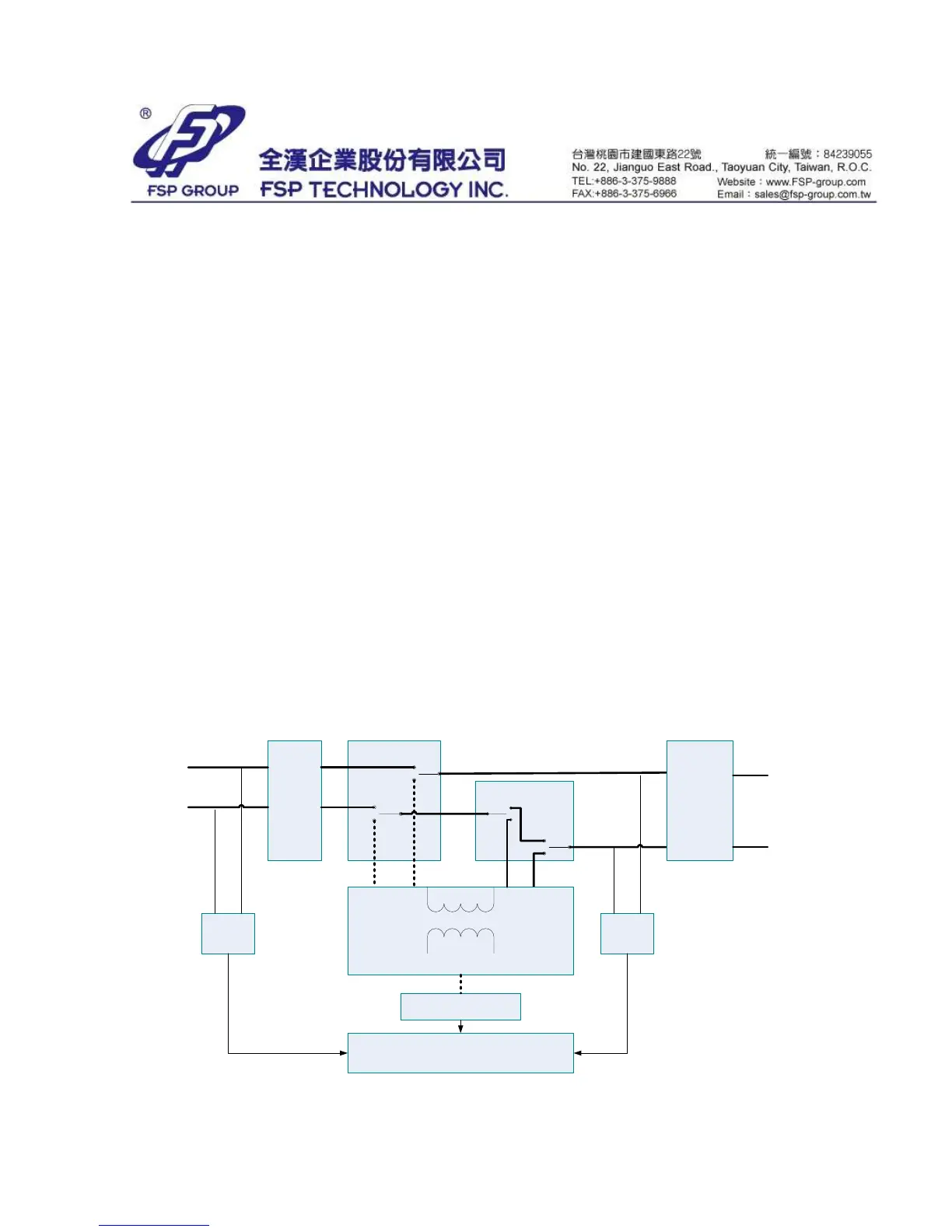
2.6 CPU (MOTOROLA/ MC68HC908JL8CSP)
The Central Process Unit
2.7 Electricity Switch
It controls the +5Vdc and +12Vdc supplies.
+5Vdc and +12Vdc Control Power Generator.
Provide +5Vdc (generated from 7805 regulator) and +12Vdc power supply.
2.8 Charger:
The source for the Charger comes from the mains through the transformer and
full-bridge inverter. The charger is controlled with high frequency technology and
the acceptable charging voltage is 13.6~13.9V.
2.9 I nverter Circuit:
The inverter circuit is based on a full-bridge circuitry.
2.10 I nterface Circuit:
The UPS display device contains one LED (or three-LED as option) and one switch.
2.11 Batteries:
Acts as a power supply source while the UPS is on battery mode. Different types
of batteries are used for different models of UPS:
450VA: 12V4.5Ah *1pc or equal capability
650VA: 12V7Ah *1 pc or equal capability
850VA: 12V9Ah *1 pc or equal capability
EMI
Filter
Main Relay
Buck Relay
Boost Relay
O/P Relay
O/P-N
O/P-L
I/P-N
I/P-L
Transformer
Inverter/Charger
Battery
Line
Sense
O/P / Load
Sense
CPU
Figure S-1 Block Diagram