Assembly Section 3-3
FB42 08/01
© 2004 Alamo Group Inc.
ASSEMBLY
ASSEMBLY
R 08-12-99
11,12,13
14,15
1
7,8,9
3
9,10
22, 23
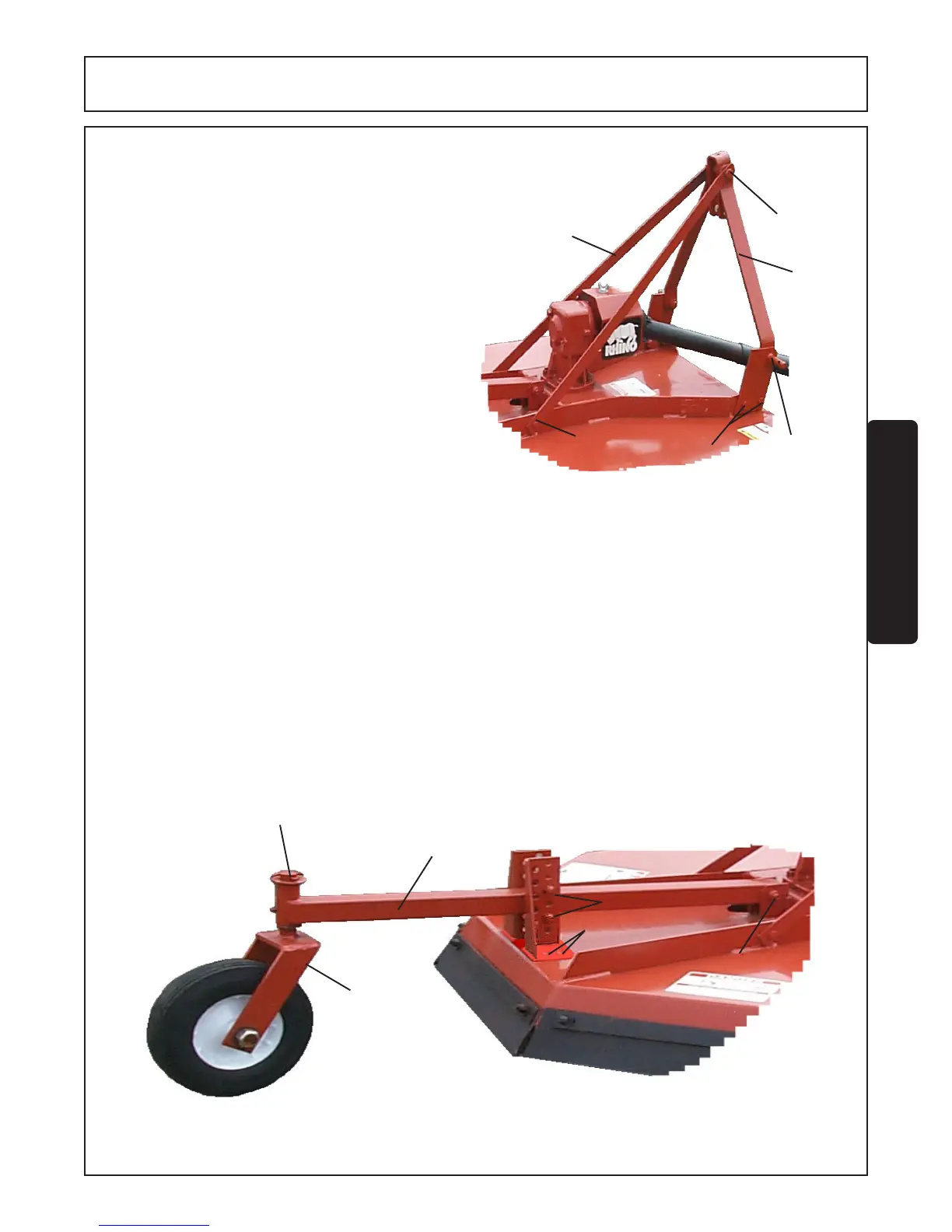
FIGURE 4. A-Frame Installation
17, 18
16
8,9
19
5,6
20, 21
A-FRAME INSTALLATION (FIGURE 4)
1. Attach “A” Frames (1) to inside of welded hitch
brackets on Mainframe, insert Hitch Pin (12), Bush-
ing (15), flatwasher (11), lockwasher (14) and install
nut (13). Then attach to lug hitch with bolt (22) and
locknut (23).
2. Install the lift straps (3) on inside of top rails on
mainshield (behind gearbox mount) and attach with
1/2" x 1-1/2" bolts (10) and locknuts (9).
3. Insert spacer (7) between A- frames (1). Insert
3/4" x 6" bolts (8) thru hole in lift straps and spacer
(7). Secure with 3/4" locknut (9).
TAIL WHEEL INSTALLATION (FIGURE 5)
5. Align tailwheel beam weldment (16) between pivot brackets located behind gearbox mount on mainshield
weldment. NOTE: Long side of caster fork pivot tube is positioned up. Attach tailwheel beam weldment to
mainshield with 5/8" x 3-1/2" bolt (5) and locknut (6).
6. Insert caster fork assembly (19) into tailwheel beam weldment (16). Install washer (17) and secure with cotter
pin (18).
7. Place tailwheel adjusting brackets on to deck and secure with bolt (20) and locknut (21).
7. Position tailwheel beam weldment between tailwheel adjusting brackets on mainshield weldment and secure
with two 1/2" x 3" bolts (8) and locknut (9).
8. Tighten all bolts to the proper torque.
FIGURE 5. Tail Wheel Installation.