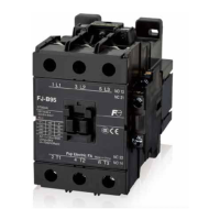
z Magnetic Contactor (DC operated)
FJ-B06/G
FJ-B09/G
FJ-B12/G
35mm
FJ-B18/G
35mm
FJ-B25/G
FJ-B32/G
35mm
10
7.7
(28)
107
88
2343
18.5(~20.5)
14.5
8.5
(68)
81
43
35
60
(48~)52
34
*2
*1
*1
1
2
Coil terminal
M3.5
Auxiliary terminal
M3.5
Main terminal
M3.5
Mounting hole
2-M4
Panel drilling
117(Mounting rail height: 15)
Auxiliary
contact
Wiring diagrams
1NO
(1a)
1NC
(1b)
14
135/L33/L21/L1
2/T1 4/T2 6/T3
A2A1
1/L1
2/T1
A1 A2
6/T34/T2
3/L2 5/L3 21
22
Mounting dimension: mounting according to (1) or (2)
(1)…35×60
(2)…34×(48~)52
Mount it using the 2 holes on the diagonal line.
108
88
8.5
43 23
49 20
81
118(Mounting rail height: 15)
*1
(28)
14.5
10.5
13138
(78)
53
7.7
*2
*1
Coil terminal
M3.5
Auxiliary terminal
M3.5
Main
terminal
M4
Mounting hole
2-M4
Panel drilling
18.5(~20.5)
Auxiliary
contact
Wiring diagrams
1NO
(1a)
1NC
(1b)
35
60
(48~)52
34
1
2
14
135/L33/L21/L1
2/T1 4/T2 6/T3
A2A1
1/L1
2/T1
A1 A2
6/T34/T2
3/L2 5/L3 21
22
Mounting dimension: mounting according to (1) or (2)
(1)…35×60
(2)…34×(48~)52
Mount it using the 2 holes on the diagonal line.
7.7
6
Coil terminal
M3.5
Auxiliary terminal
M3.5
Main terminal
M3.5
61(Mounting rail height: 15)
36
49
48
31
45
8.7
(Note) Please note that the terminal of the control
coil has polarity.
Mount it using the 2 holes on the diagonal line.
Auxiliary
contact
Wiring diagrams
1NO
(1a)
1NC
(1b)
14
13 5/L33/L21/L1
2/T1 4/T2 6/T3
(-)
A2
(+)
A1
(-)
A2
(+)
A1
1/L1
2/T1
6/T34/T2
3/L2 5/L3 21
22
Mounting hole
2-M4
40
35
Panel drilling
Mass: 0.17kg
Mass: 0.57kg
Mass: 0.59kg
*1 For front mounting aux. contact blocks mounted.
*2 For two side mounting aux. contact blocks mounted.
*1 For front mounting aux. contact blocks mounted.
*2 For two side mounting aux. contact blocks mounted.
Information subject to change without notice
17
FJ Series
 Loading...