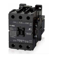
Ratings (IEC60947-5-1, GB14048.5)
z Bifurcated-contact
Type Conventional
thermal
current [A]
(rated making
current)
Making and
breaking
current (AC)
Rated operating current [A] Minimum
operating
voltage ·
current
Rated operating
voltage [V]
AC-15
(Coil load)
AC-12
(Resistive
load)
Rated operating
voltage [V]
DC-13
(Coil load)
DC-12
(Resistive
load)
SKH4AB
SKH4GB
10
30 AC100-120 3 6 DC24 2 3
DC5V, 3mA
30 AC200-240 3 6 DC48 1 2
10 AC380-440 1 6 DC110 0.3 1.5
5 AC500-600 0.5 3 DC220 0.2 0.5
(Note) Generally, when the atmosphere does not contain dust and corrosive gases, the failure rate is Level 10
– 7
.
Ratings of additional auxiliary contacts are the same as shown in the above table.
z Single-contact
Type Conventional
thermal
current [A]
(rated making
current)
Making and
breaking
current (AC)
Rated operating current [A] Minimum
operating
voltage ·
current
Rated operating
voltage [V]
AC-15
(Coil load)
AC-12
(Resistive
load)
Rated operating
voltage [V]
DC-13
(Coil load)
DC-12
(Resistive
load)
SKH4ABH
SKH4GBH
10
60 AC100-120 6 10 DC24 4 8
DC24V, 10mA
60 AC200-240 3 10 DC48 1 3.5
60 AC380-440 1.5 10 DC110 0.5 2.5
30 AC500-600 1.2 5 DC220 0.25 0.8
(Note) Generally, when the atmosphere does not contain dust and corrosive gases, the failure rate is Level 10
– 7
.
Ratings of additional auxiliary contacts are the same as shown in the above table.
List of optional combination units
Product name
Type Descriptions
Used with
Auxiliary contact unit
(Top mounting)
Bifurcated-contact Compact
SZ1FA11 Contact arrangement: 1NO1NC
SKH4B
SKH4BH
Single-contact Compact
SZ1FA11H Contact arrangement: 1NO1NC
Bifurcated-contact
SZ1KA40 Contact arrangement: 4NO
SZ1KA31 Contact arrangement: 3NO1NC
SZ1KA22 Contact arrangement: 2NO2NC
SZ1KA13 Contact arrangement: 1NO3NC
SZ1KA04 Contact arrangement: 4NC
SZ1KA20 Contact arrangement: 2NO
SZ1KA11 Contact arrangement: 1NO1NC
SZ1KA02 Contact arrangement: 2NC
Single-contact
SZ1KA40H Contact arrangement: 4NO
SZ1KA31H Contact arrangement: 3NO1NC
SZ1KA22H Contact arrangement: 2NO2NC
SZ1KA13H Contact arrangement: 1NO3NC
SZ1KA04H Contact arrangement: 4NC
SZ1KA20H Contact arrangement: 2NO
SZ1KA11H Contact arrangement: 1NO1NC
SZ1KA02H Contact arrangement: 2NC
Coil-surge absorption unit
SZ1KZ1 Built-in varistor: AC24-48V
SKH4AB
SKH4ABH
*1
SZ1KZ2 Built-in varistor: AC48-125V
SZ1KZ3 Built-in varistor: AC100-250V
*1 DC-operated SKH4GB, SKH4GBH with built-in varistors.
Dimensions, mm
SKH4B
(34)*1
(17)*2
Mounting hole
2×M4
6
40
35
Coil terminal
M3.5
Terminal
M3.5
61(When the height of the guide rail is 15)
36
49.5
7.7
48
31
45
8.7
34
33
A2 (-)
A1 (+)
※
13 21 31 43
322214 44
※
2NO2NC
4414 22
432113
*When it is DC-operated
Mass: 0.14kg(SKH4AB, SKH4ABH)
0.17kg(SKH4GB, SKH4GBH)
[NOTE]
*1: Mount the auxiliary contact unitSZ1KAWhen it is square
*2: Mount the auxiliary contact unitSZ1FAWhen it is square
※
※
※
※
※
※
A1 (+)
A2 (-)
● Mounting screws: 2-M4
Align the two mounting holes on the
diagonal during mounting. .
44
43332313
14 24 34
Contact arrangement
4NO
3NO1NC
A2 (-)
A1 (+)
Mounting hole
dimension drawing
-A244322214
+A1NO43NC31NC2113 NO
Information subject to change without notice
35
FJ Series

 Loading...