Do you have a question about the FujiFilm DR-ID 1300 and is the answer not in the manual?
Highlights the importance of observing warnings and instructions to avoid physical hazards and accidents during installation and servicing.
Instructs supervisors to check if the machine is installed in a patient environment or not, defining patient, medically-used, and non-medically used rooms.
Addresses precautions related to electromagnetic compatibility (EMC) and compliance with relevant standards for the DR-ID 1300PU.
Describes the necessary installation space and precautions to avoid interfering with patient or customer movement.
Details the electrical specifications for the DR-ID 1300PU, including frequency, input voltage, and power source conditions.
Outlines actions to take in case of failure, distinguishing between failures attributed to the customer and the manufacturer.
Provides conditions to determine customer-attributed failures and actions to take, including repair costs and replacement procedures.
Lists conditions for determining if SE failure is due to customer handling, such as external form deformation or water damage.
Describes repair actions for customer-attributed failures, including primary repair responsibility and cases where repair is not possible.
Defines conditions for manufacturer-attributed failures and the corresponding actions, including repair costs during the guarantee period.
States that if failure conditions are not attributed to the customer, they are determined to be attributed to the manufacturer (FUJIFILM).
Outlines actions for manufacturer-attributed failures, including repair costs during the guarantee period and cases where repair is not possible.
Provides instructions for disposing of the machine and its components in compliance with local regulations and environmental considerations.
Provides an overview of the DR-ID 1300 system, including features of the DR-ID 1305SE and system configuration examples.
Details the features of the DR-ID 1305SE, highlighting its long-length radiography capabilities and advanced imaging technology.
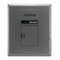
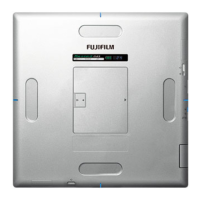
Describes the general configuration of the DR-ID 1300PU, including external views, functions, and status lamp indications.
Details the external view and functions of the DR-ID 1305SE and DR-ID 1300MP, including their descriptions and status lamps.
Presents block diagrams for the system, SE, and MP, illustrating component interconnections and signal flows.
Illustrates the system block diagram, showing connections between SE, MP, CSL, and X-ray control box with cable types.
Provides a detailed block diagram of the SE, showing connections between various boards like RMV, POW, COC, and HUB.
Presents the block diagram for the MP, illustrating connections between CPU, FPGA, MPC54B, and MPL65A boards with various components.
Outlines the different types of calibrations performed by the machine, including background, offset, defect, and marker calibrations.
Provides an overview of troubleshooting for SE (FPD) malfunctions, emphasizing error log checks and careful unit replacement.
Details the process of troubleshooting using the RU PC-TOOL ERROR DB to view error logs and check error codes.
Describes how to start the RU PC-TOOL, back up the error log, and start the ERROR DB to view the error log.
Guides on grouping errors by occurrence time and locating the first error responsible for the encountered trouble.
A comprehensive table listing error codes, their names, occurrence conditions, and probable causes and remedies.
Explains how to analyze errors by checking the lighting state of the status lamps (LEDs) on the SE (FPD).
Provides guidance on analyzing abnormal images, including information required for efficient analysis and potential calibration needs.
Provides actions to take for the 10753 error, including BIOS settings, OS version updates, network configuration, and F-Secure installation.
Details how to change the PC's BIOS settings to suppress the 'error 10753 (MP connection error)'.
Provides procedures for updating the MP OS version, including preparations and the update process itself.
Explains how to check and modify the network configuration to prevent communication errors by connecting devices in a star topology.
Describes actions for the '10753 error (MP communication disconnection)' that may occur when F-Secure is installed.
Details the analysis procedure for the 10753 error by examining logs, distinguishing between normal and abnormal cases.
Highlights precautions for component removal/reinstallation, including electrical hazards, grounding, and handling of boards and screws.
Provides safety warnings and cautions for servicing the MP, emphasizing power OFF procedures and handling of fuses.
Highlights warnings and cautions for servicing the SE, emphasizing power OFF, avoiding static discharge, and not scratching the ASIC.
Provides procedures for updating or downgrading the MP OS version, including checking the current version and performing the update.
Guides on checking the MP OS version using the MUTL and comparing it with the version indicated in the Readme.txt file.
Details the procedure for updating the MP OS version, including preparations and executing the fwupdate.bat file.
Provides procedures for downgrading the MP OS version, similar to updating but using a different version of the installer.
Offers countermeasures for errors generated when mounting the DVD drive, such as creating folders or checking device names.
Explains defect calibration and lag calibration procedures, to be performed when problems arise due to artifacts or other factors.
Details procedures for defect calibration, including selecting the SE, setting operation, exposing, and creating/checking data.
Details procedures for defect calibration using the RU PC-TOOL, including selecting SE, inputting SE No., and setting operation.
Provides instructions for installing the RU PC-TOOL for MC V3.x or earlier versions.
Details the procedure for installing Internet Explorer 11, which is necessary for using the DR Maintenance Software on Windows 7.
Explains how to install FPGA software onto SEs with new FPGA memories, including confirming resolution details and MC software version.
Introduces the DR Maintenance Software, its operating environment, and how to start it.
Details procedures for updating software for MP and SE units, including checking current and updated versions.
Guides on updating the MP software by selecting the target MP, getting version information, and installing the updated version.
Provides instructions for updating SE software, including selecting the target SE, getting version information, and installing the updated version.
Details various calibration procedures for the SE, including Offset, Gain, Defect, Lag, and Long Panel calibrations.
Guides on performing SE calibration, including offset, gain, defect, lag, and long panel calibrations.
Describes calibration procedures specifically for the DR-ID 1305SE long panel, including offset, gain, defect, lag, and long panel calibrations.
Provides procedures for backing up and restoring configuration information and error logs in the HDD.
Guides on backing up and restoring SE correction data, per each SE1 sheet or in batches.
Details backup and restore procedures for DR-ID 1305SE correction data for each panel unit sheet or in batches.
Provides procedures for backing up and restoring MC configuration data.
Introduces the PC-TOOL, a tool for service engineers to set and check RU functional conditions via the CL.
Details various calibration procedures for the SE, including offset, gain, defect, lag, and marker calibrations.
Carries out offset calibration without exposure, generating correction data for still image radiography.
Performs gain calibration under specific exposure conditions, noting precautions about tube position and artifacts.
Guides on defect calibration, including selecting SE, setting operation, exposing, and creating defect data.
Details lag calibration procedures, including SE selection, operation setting, exposure, and creating lag data.
Explains marker calibration for synthesizing images without misalignment, including preparing for calibration and exposing.
Guides on setting the IP address of the SE, emphasizing connecting only one SE to avoid duplicate IP address errors.
Details procedures for checking and updating SE application software version for all three panel units.
Presents a flowchart outlining the installation procedures for the RU PC-TOOL.
Details the necessary tools, jigs, and measuring instruments required for installation.
Provides step-by-step procedures for installing the MP, including removing covers, checking the power cable, and connecting cables.
Explains how to connect the X-Ray shot cable based on grid oscillation mode (Steady Grid, Bucky Contact, Bucky AC).
Provides cautions and procedures for installing the SE, emphasizing power OFF, disconnecting SE cable, and battery removal.
Outlines the flow for installing RU software programs after DX Console setup, including network settings and IP addresses.
Guides on installing and setting the NIC board in the DX Console, including renaming connections and enabling Telnet Client.
Details the procedure for installing the RU PC-TOOL, including inserting the install disk and executing the setup wizard.
Explains how to start the DR Maintenance Software by opening Internet Explorer and selecting 'INSTALLATION'.
Guides on checking and updating the MP Application Software Version, including making sure the install disk is inserted.
Details procedures for checking and updating SE application software versions, including selecting target SE and clicking [INSTALL].
Guides on setting the IP address of the SE, emphasizing connecting only one SE to avoid duplicate IP address errors.
Explains the importance of transferring correct data to the panel unit after installing machine-specific data to prevent artifacts.
Provides procedures for changing IP addresses of SE/MP/MC and FTP server from default values, with cautions on duplicate addresses.
Details image calibration procedures, including offset, gain, defect, and marker calibrations, with precautions on background calibration.
Guides on performing offset calibration, emphasizing starting the system, cleaning the SE plane, and adjusting X-ray tube position.
Details gain calibration procedures, including exposure conditions and precautions on tube position and artifacts.
Explains how to check calibration results by backing up SE correction data and opening specific files with Word Pad.
Guides on performing marker calibration for synthesizing three panel unit images into one long-length image without misalignment.
Provides methods for checking image problems like irregularities, density issues, white blank portions, and sensitivity problems.
Details how to check for image irregularities, density problems, white blank portions, and sensitivity issues.
Guides on starting the RU PC-TOOL, clicking [ERROR DB] to check the error log, and clearing the log.
Covers final checks, including checking the SE for damage and checking the status of MP and SE boards.
Discusses precautions related to image unevenness in the DR-ID 1300, including mechanism, stitching area, and example images.
Explains the technical key issues causing unevenness at the stitching area, related to X-ray absorbency and scattering.
Shows examples of images before and after correction of unevenness at the stitching part, illustrating improvements.
Presents example images of the stitching part, including discontinuous grained patterns and differences in image density.
Illustrates the difference in image density between panels, particularly in the stitching area, due to object structure.
Discusses image density differences in panels, especially with Virtual Grid processing on thick objects.
Shows image density differences between panels, particularly horizontal direction variations along the stitching area.
Explains white and black bands in band-like images caused by unevenness correction using vertical and horizontal directions.
Describes artifacts like long tail appearance in center panel images for high-contrast, horizontally-long objects.
Guides on performing defect calibration, including exposure conditions, selecting SE, and creating defect data.
Details procedures for lag calibration, including selecting SE, setting operation, exposing, and creating lag data.
Explains how to check calibration results by backing up SE correct data and opening specific files with Word Pad.
Guides on performing defect calibration using RU PC-TOOL, including SE selection, inputting SE No., and setting operation.
Provides procedures for lag calibration using RU PC-TOOL, including SE selection, inputting SE No., and setting operation.
Explains how to check calibration results using RU PC-TOOL after calibration.
| Brand | FujiFilm |
|---|---|
| Model | DR-ID 1300 |
| Category | Medical Equipment |
| Language | English |